|
tamar
Posts: 804
Registered: 5-1-1989
Location: Gouda
Member Is Offline
Mood: A new beginning 
|
|
posted on 14-2-2019 at 11:35
|

|
|
Ford GT LM, the road to Le Mans 1/32
The Ford GT LM (3rd Gen)1/1
Ford returned to Le Mans in 2016 as a factory team in a blaze of glory, its modern GT winning the GTE LM class exactly 50 years after the original
GT40's 1-2-3 in 1966. Although it was always intended to take its place among the world’s most desirable ultra-high performance sports cars,
make no mistake, the third generation Ford GT was conceived, designed and built with one priority in mind: Win the 24 Hours of Le Mans on the 50th
anniversary of Ford’s fabled victory at le Sarthe in 1966. So for that one..mission accomplished.
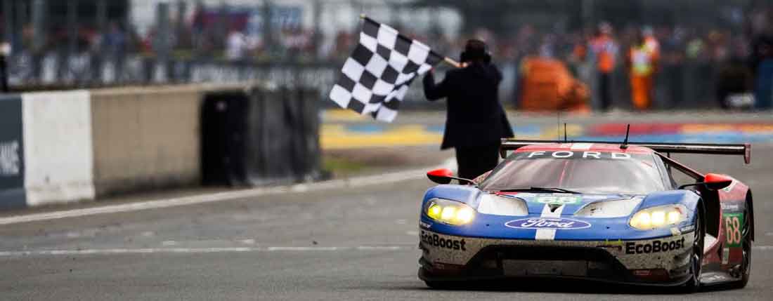
Some may say that the Ford GT LM is a masterpiece in design, echoing the iconic shape of the Ford GT40 that Bruce McLaren and Chris Amon piloted to
victory in the “ronde infernal”,while taking every possible advantage of the Fédération Internationale de l’Automobile’s regulations to
create another Le Mans winner. With a miniscule frontal area and dramatic “flying buttresses” the Ford GT cuts through the air on the Mulsanne
Straightaway like the proverbial knife through butter
with plenty of of help from a 3.6 liter, twin turbo Ecoboost V6 engine producing 530 horsepower and 494 ft-lb torque.
Some may say that by doing so Ford has moved the goal post in GT "beyond" what was intended by the "spirit of the rules". That it is a prototype
clad in GT bodywork.
In any case the combination delivered a dramatic Le Mans win in the car’s inaugural campaign, along with several other victories in World Endurance
Cup and IMSA competition, indelibly stamping the Ford GT as worthy successor to its legendary namesake...and that of other goal post movers like the
(mid engined) Porsche 911 evo and Toyota TS020 GT-One of two decades ago.
The Ford GT LM (3rd Gen)1/32
With such a new Icon on the racetracks it didn't take long before both the major players in the slot, Carrera and Scalextric announced that they
would do the GT LM.
As did the small volume 3DP manufacturers The Area 71 and Arrow slot. With both of them acquiring and entry for the 2017 Oxygen LM 24hrs it was the
latter that was to give the Ford GT its debut in DiSCA competition (TA71 withdrew its entry two months for the race). Alas no copy of a debut victory
like its big brother.
The Arrow slot Ford faired well, the 3D printed body and chassis finishing second in class and 5th overall, but major succes came a year later when
Spanish team Ditslot i3D entered a development 3DP chassis with simple slot.it pod and a similar 3DP body. They not only took first in class but also
1st place overall.
Does this make the Ford GT LM an absolute winner in the slots as well? Well it definitely has potential, its low, wide and has a long wheelbase. With
slotcars in general running with the same engines and weights that's definitely an advantage. But Ditslot i3D did not claim its victory by having a
much fast(er) car.
By times our Corvette C7R was faster and by a large margin Rockingham's Toyota LMP1 had the legs on the Ford GT.. at least over a single lap.
The true merit of the Iberian team was its incredible consistency, punching out fast times lap after lap (with a slight punch left right and center),
staying on track all the time and only pitting half a dozen times to change tires. It was an impressive Team result, not specifically down to the fast
pace of the Ford itself.

The Road to Le Mans, 1/32
As I post this its just 9 weeks till the 8th edition of the DiSCA Le Mans 24hrs, some of you that have read my other post will know that for the past
six months "my road" to Le Mans was heading in a totally different direction, or should I say a totally different car. Although good progress has
been made on the BMW M8 GTE project, the M6 GT LM test car winning its class and 3rd overall @ the Suzuka 6hrs, we've got some the delays on the M8
that will curtail the R&D program to such an extent that we decided to switch to plan B. And Plan B is to stick the #18 on the #68 Ford GT-LM and run
that car @ the Le Mans 24hrs.
Here's an "artist impression" on what's going to be the #18 Ford Monkeytown Team NL Ford GT-LM.
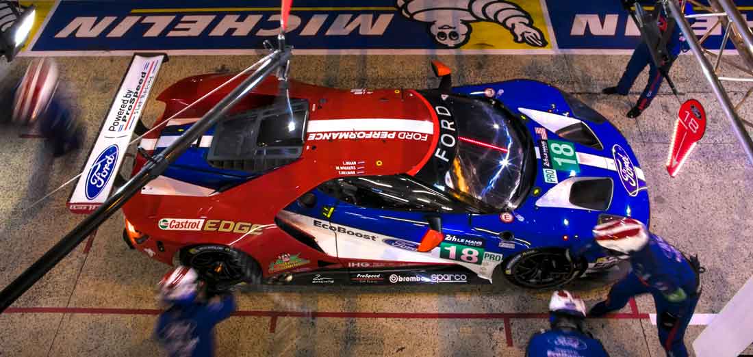 #18
Ford MonkeyTown Team NL, Ford GT LM GTE #18
Ford MonkeyTown Team NL, Ford GT LM GTE
Part of the reasoning behind this late switch to another car is that we're not totally starting from scratch. The Ford GT has been on the workbench
next to the BMW M6 for some weeks now and I've even made posts on some of the work I already did on the Ford here and here
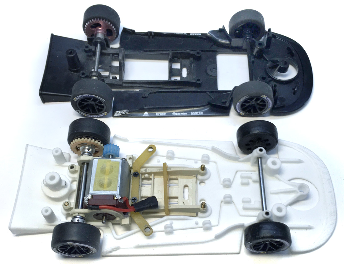
Via this topic I hope to keep you updated on what work will be done to get our Ford which will be based on the Scalex RTR car..with a Prospeed chassis
in the following 9 weeks on our road to Le Mans 1/32
To be continued
|
|
|

|
tamar
Posts: 804
Registered: 5-1-1989
Location: Gouda
Member Is Offline
Mood: A new beginning 
|
|
posted on 17-2-2019 at 23:10
|

|
|
The Road to Le Mans 1/32: 8 weeks and
counting
Finally have a short moment to post an update, its been a busy week and a half, spend most of my free time in the "workshop" getting the
Ford ready for its first shakedown.
That clock just keeps on ticking.
Most of last weeks work was focussed on categorizing and analyzing what body and chassis modifications needed to be done to fit the
chosen race set-upand then implementing them on the first Prototype chassis.
For a race like the DiSCA Le Mans 24hrs that means a set-up that has been tried and tested, evolution instead of revolution, experience gained the
hard way 
So it won't be much of a surprise for most of you to see the first pics of the Mark I chassis with a slot.it sidewinder pod.
I'll be building on the experience gained in the last two editions with the DiSCA Proton Porsche and the SRFH Corvette C7R.
Taking stock...
So the first thing I always do when I start a new project is to open a new excel sheet and take stock, I've got one for every car I've build in the
last 4 years.
Each data sheet contains all the parts used for the car during the build & testing and the race(s). It list part nr, dimensions and most important
their weight.
With most of the specs for the running gear pretty much at a constant, the sheet allows me to calculate what consequences a specific a set-up will
have on the weight of the car.
But for each car the chassis and certainly the body can be very different.
So here I usually start with noting down the values for the Stock parts (if there is a stock base car) in the first column and set target values in
the last.
During the build a new column is added for each test so I can keep track what progress (if any) has been made.

From left to right: Complete Stock body, rear Wing support &
wing, Rear wing, Stock Windows, Interior & motor detail, Detail parts, Bare Inner body, Bare outer body
...and making plans
Taking stock also helps with making plans as it becomes pretty obvious where the biggest gains can be made. With a target weight of 16 gr (need 3gr
for lights) the Ford is pretty good to begin with.
Ditching the rear wing support section for something lighter and a vacformed interior and we're a good way towards our target.
But because the Ford has such a small and low body I won't be able to make such serious weight gains as I did with the Carrera M6.
So like very other car I've build to DiSCA spec..every 10th of a gram will matter.
Besides making masters for Vacformed parts, modifying the body to make room for the SW configuration will also needed to be done.
In my "S- can conversion" post I mentioned
that little or no body mods would het been required for Scalextric to have fitted their regular S-can.
And that even a SW configuration would have been possible...for a Stock chassis. But for a DiSCA spec car with offset pods and 1 -1,5 mm suspension
travel..its a different story.
Suspens(ion)
One one of the reasons why the Ford became our plan B was that besides a Scalex base car I also had a ProSpeed 3DP chassis.
Although its designed to be compatible with slot.it pods it did not have any pick up points for the Evo-6 springs.
But like with the M6, Stefan was willing to incorporate any changes I would need in new chassis versions.
I would modify the first chassis to my desire and use that as a prototype to test the changes, evaluate and after Stefan added them to the design have
a Mark II version printed. Within the 8 weeks window that would give us possibly 3 development cycles, way to go ProSpeed. :thumbsup:
So the first thing I did was add another layer of on top of the rear of the chassis, covering the general area where I thought the suspension and body
adjust screws could be placed. Using 1,5 mm thick plasticard this would give me enough "depth" to countersunk the suspension screws.
I've always been a fan of side suspension when running on Ninco, and the wider I can spread my suspension points the better.
So the good news with the Ford was that (unlike most other GT's) the wide Evo spring arms do fit under the body.
The bad news was that there's no room to mount any spring on top. So I went through my spares box and dug up varies springs and suspension bits and
pieces.
The shape of the body and the pod more or less dictated where I would be able to mount the springs.

I had some parts on order, but did not want to wait till they arrived, and I had cut off the evo 6 mounts on all the SW pods we prepped for the
Porsche and C7R. The only pod left was a 0,5mm offset..for a prototype it would have to do. Besides having Side suspension I also wanted to be able to
adjust the spring screws without having to open the body..so some kind of top nut retainer was needed. Turned out the Thunderslot top nuts with
Scaleauto screws was the only combination with plenty of travel but still low enough to fit under the body...well almost 
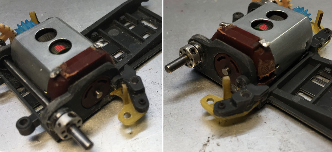
So here are the suspension adaptors I fabricated from 1mm GRP, just thick enough to cut a thread in so I could mount them with grub-screws (lighter
then normal screws cause they have no head) to the OEM slot.it mounts.
And just thin evenough to slide between the chassis and the suspension arms. Must say easier said than done.
Although officially you could call these adaptors Mark I, I must have fabricated, and oops dropped on the floor and lost for ever..half a dozen of
these tiny parts.
Inner body
A very interesting feature of the Scalex Ford GT is that they've conveniently designed their casting, separating the body in an outer and inner body
shell.
Conveniently as it was very helpful to just be able to use the inner body shell dismounting it a zillion times to see if it fits, and if not..where it
rubs.
An oh boy did it rub. On the workbench all looks fine with plenty of clearance, but on the track with all the body float and pod travel everything
would start to foil and hinder free movement.
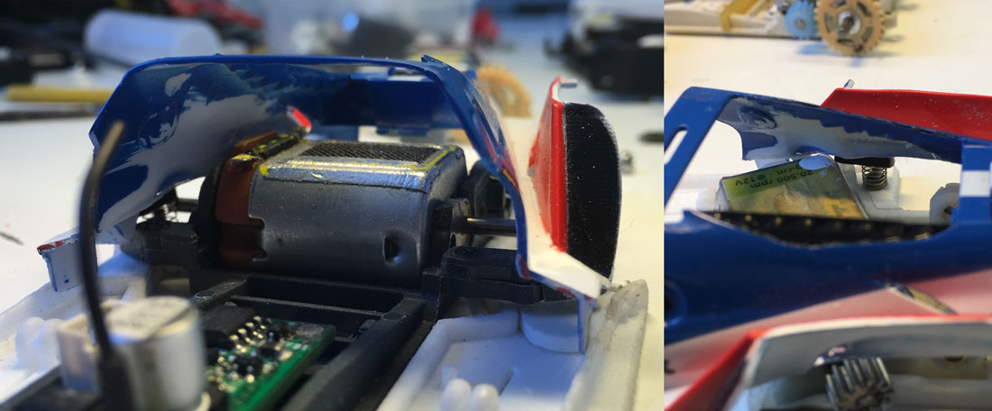
No matter what I tried, I could not get the radiators to clear the top suspension nuts, so they had to move, or more accurately they had to rotate a
bit.
Below you can see how I cut them of the inner shell and remounted them at an slight upward angle. Now I had room enough for the suspension mounts with
their top nuts to move freely.

Ok that's it for now, got more work planned for 2 night, got a master for the interior to finish, mould and cast.
As a preview of post to come.....see pic below..cause yes...I did manage to finish the Ford GTLM Mark 1 for last Sunday's roll out and shakedown.
The results were promissing...
to be continued
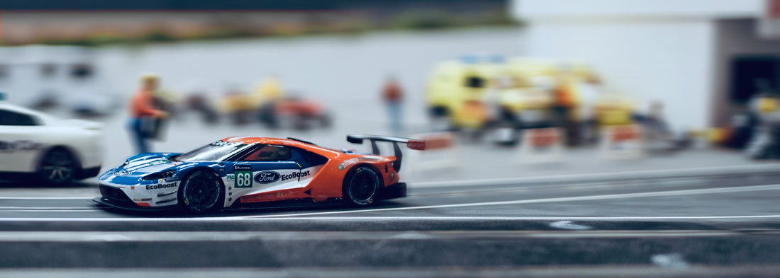
Ford GT LM Mark 1 leaving the Pits @ Suzuka for its first
Shakedown
|
|
|

|
tamar
Posts: 804
Registered: 5-1-1989
Location: Gouda
Member Is Offline
Mood: A new beginning 
|
|
posted on 17-2-2019 at 23:10
|

|
|
The Road to Le Mans 1/32: 7 weeks and
counting
Hello guys, just seven weeks till the start fo free practice, time for a quick update, as mentioned in my last post this week's work focussed
on getting the masters for the vacformed parts ready for silicone casting.
No completely finished yet, still have more work on the cockpit and driver seat, but the motor compartment is finished
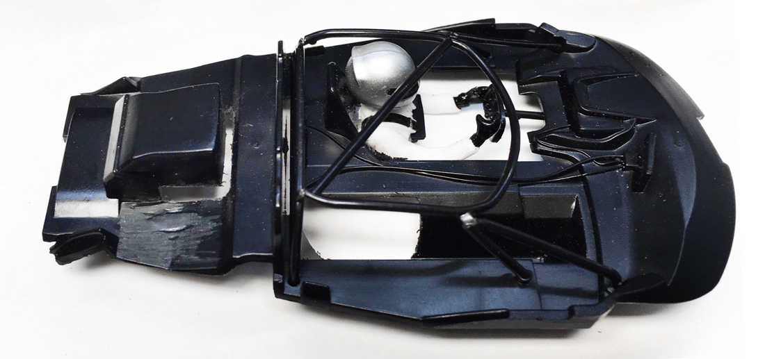
Stock Scalex interior tray, already with serious chunks dremmeled away, Scalex Motor detail and half of driver seriously lacking.

On the left Stock Scalex driver now with legs and new tray for motor compartment, on the right with new seat and all Motor detail added.

On the left , right side view of interior , on the right interior split up in parts to be vacformed separately. First and probably last time anyone
will see the scratch build intake manifold, but at least I'll know its there.
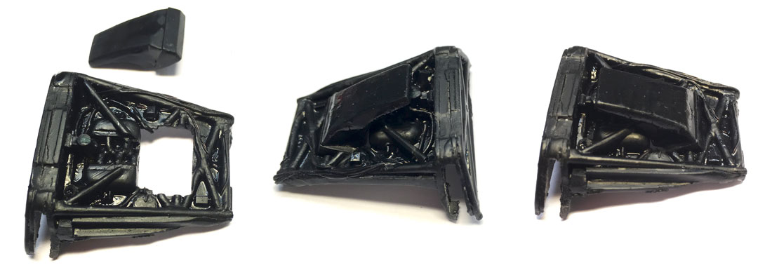
Motor compartment with a coat of Vallejo plastic primer added, this to seal and close any gaps between the glued parts on the master (and looks much
better too)
More words to follow, gotta work
|
|
|

|
tamar
Posts: 804
Registered: 5-1-1989
Location: Gouda
Member Is Offline
Mood: A new beginning 
|
|
posted on 25-2-2019 at 10:12
|

|
|
The Road to Le Mans 1/32: 6 weeks and
counting
Another week has flown by, work on the Ford is making good progress, but I'm running seriously behind with my post updates. Last week I
finished the master of the cockpit, vacformed the first prototype and ran a second test in Best, checking the modified body for any clearance issues
with the modified chassis. But let's pick up where I left with my last post.
In the driving seat
As I mentioned before, the stock Scalex interior was lacking a bit of detail..and half of the driver ..not to mention the rudimentary driver seat.
On almost all slot cars the driver and his position in the car are hideously incorrect and when they make a vacformed version of the stock
interior most of them will look like shapeless..blobs. Seems like if you want to save a bit of weight you should not care on how it looks...well....
I do.
With all the space you need for the chassis bits (not to mention the Oxygen Chip) there's no way to replicate the depth of the interior in true
scale, so its more about creating a suggestion of depth and detail.
Doesn't take much to do so, a few rectangles of styrene, some wires here and there. I'd collected tons of reference images..but in the end you just
have to wing it.
It does help that on contemporary Sportscars the seats are thick and well padded. And with the HANS devices the helmet and driver have got a
vacformable shape.
A bit of putty here and there to properly "seat" the driver, used some thin foam I had in my bin box for the padding.
Created a bit of extra room for an Anglewinder Flat-6 in the passenger compartment so the interior would fit both SW and AW configurations, at least
so I hope 
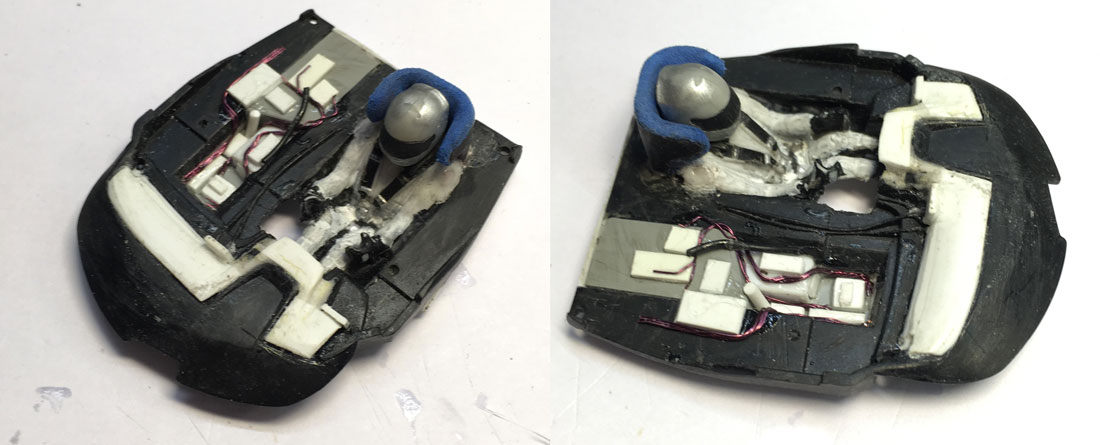
Going pear shaped
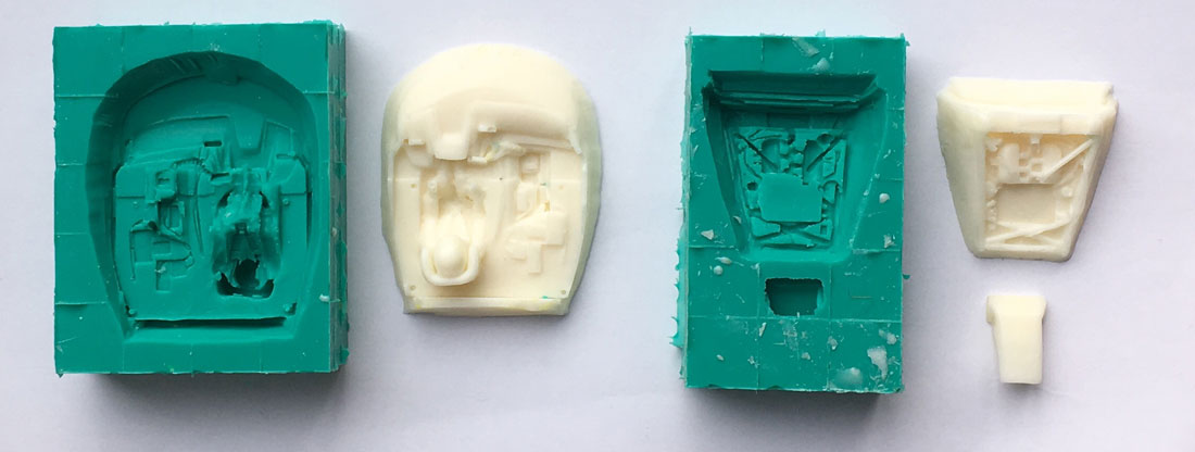
Below the various steps I made to make casts of the masters. Your never to old to play with Lego, excellent stuff to make cast boxes, yeh they will
leak a bit, but nothing too bad. More important when you make vacformed masters is to keep in mind they have to be pear shaped, or beter pyramide
shaped. They have to be wider at the bottom than at the top..otherwise you won't be able to get the master out of the vac-formed PET.
A trick to help you go pear shaped when obviously your master is not...is to mount the mater at an angle in the Cast box. Lean the interior backwards
to capture the most of the dash and driver detail. Same goes for the Motor compartment, Slightly tilted backward so I can vacform both sides of the
firewall.

Negative mold to cast positive master.
So here's a picture of the "negative" silicone mold and the positive resin cast, looks nice and clean, but its actually a messy business.
Unfortunately my resin was way over date so I needed to add more harder for it so set which meant more air captured in the cast and several cast to
get a few decent ones. But for the first test it would do.
A lot of holes were drilled in the"deep" parts of the resin cast to allow the vacform machine to suck the Pet into the cavities
Here's a shot of one of the first vacformed cockpits..with just a light shot of satin black and some dabs of Vallejo white primer. Cut back stock
roll cage fits like a glove. A lot of work considering how much detail you'll actually see when he's mounted in the car...but at least it gives the
impression of a proper race driver...in the driving seat 

To be continued
|
|
|

|
tamar
Posts: 804
Registered: 5-1-1989
Location: Gouda
Member Is Offline
Mood: A new beginning 
|
|
posted on 26-2-2019 at 15:18
|

|
|
Wire to guide insertion and guide top nut
This is a copy of an answer I gave in an other forum about Wire to guide insertion The question was what method slotters preferred to insert their lead wires into the guid: Eyelets or
grubscrews?
With al the (endurance) testing for the DISCA LM 24hrs I have come to the following best procedure (I.m.o) a combination of both.
I prefer the bigger M 2,5 grub screws to secure the braids and leadwires, but will use brass eyelets to protect the lead wires from being cut. For
easy fitment I crimp the eyelets flat on the lead wires, it also keeps them from falling of while changing braids 
Pitcured below is a modified Scaleauto guide with self drilled and threaded holes for the M 2,5 grubs.
With the eyelets crimped you gain the rigidity of material for the grub screw to press on, but keep the full flexibility of the lead wire.
With tinned lead wire ends it is hard to control how far the tinn gets sucked into the lead wire, which can create a rigid and thus break point in the
wire.
M2 grubs, specially those with a pointed tip are more likely to split, cut of even miss the lead wire all together during a quick pit stop than the
broader (flat) tip of a M2,5 grub. But yes you do need to drill the hole and thread it carefully, but when done well no splitting of the guide... that
is unless you over tighten the grubscrew.
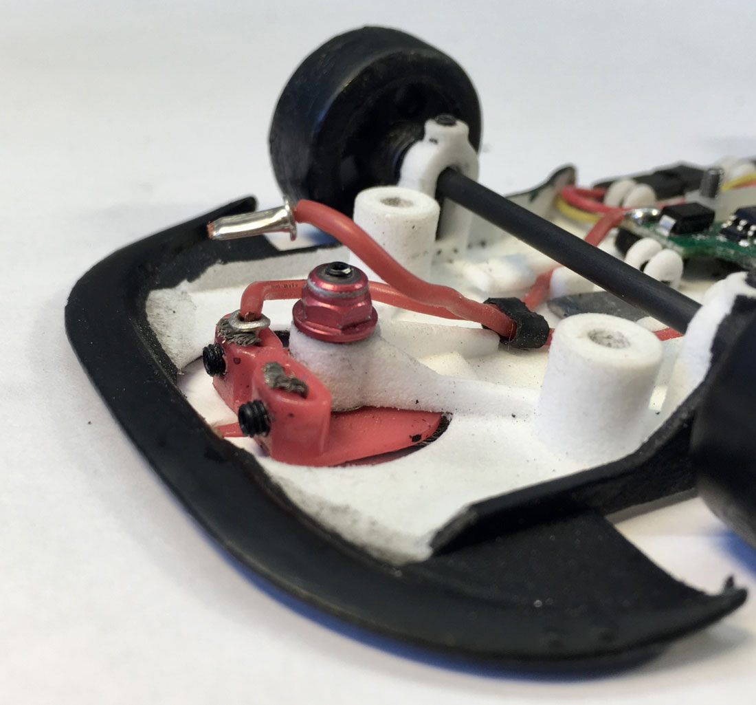
And while we're at it..the guide I mean....before you guys start asking questions about the guide nut....
Here's an other repost from older topics:
....The way I treat my guides is a crossover from the world of 1/24 racing where you use guides with a threaded stem and a guide nut.
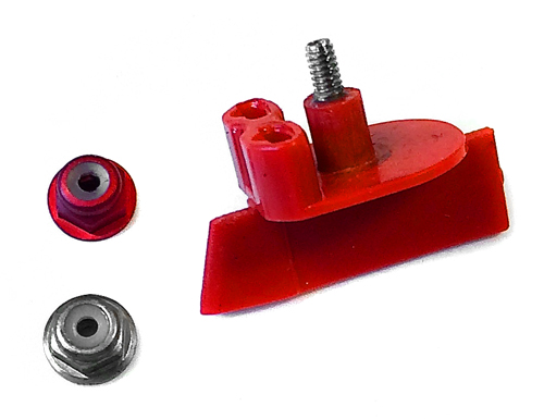
Ok what you're looking at is a Scaleauto guide with a 6mm grubb screw and a M2 aluminium locknut.
You can get these from Conrad in aluminium or anodised red and blue.
The reasoning behind me using this system is that with the regular 1/32 guide screws you have no way to lock the screw in its position.
Its eather tight or not, if you want to give your guide a bit of guide float you have to use a longer screw.
Screwing them in, in excatly the same way and perfectly straight every time is very hard to do.
By inserting a grub screw in the guide stem you only need to get it right once.
I use a m2 thread cutter to thread the hole of the guide stem, and as the cutter has a long handle its easy to get that perfectly straight and
aligned.
With the metric thread you get a much finer adjustability and the nut serves a dual purpose.
As the bottom of the nut is perfectly flat it acts as a flange and stabilizes the position and angle of the guide in the guide holder,
even when the guide holder is a bit wider than the guide stem.
And as its a lock nut its position remains fixed, no matter how much guide float I set.
As this is applicable to all cars, and not just the Ford GT.
|
|
|

|
tamar
Posts: 804
Registered: 5-1-1989
Location: Gouda
Member Is Offline
Mood: A new beginning 
|
|
posted on 28-2-2019 at 15:32
|

|
|
The Road to Le Mans 1/32: 5
weeks and counting.
Just 35 days and we should be on the ferry to Le Mans, yep starting to
count days now instead of weeks. As I needed to prep a motor pod for the MK2 chassis for the Ford,
I took some pictures during the process so
I could finally make good on a promise I made Dave Maddock some time ago..so here it goes a post on:
How to modify a Slot.it SW pod for
ballbearings and multiple gear & pinion combinations.
Light, compact and offering great handling, these
are the main characteristics why running a Sidewinder motor has become the popular choice for DiSCA spec GT's.
They have but two minor
disadvantages that with a bit of handy work are easily to overcome.
1: You can run but two gear/pinion combinations: 6,5mmø pinion with
18mmø gears or 5,5mmø pinion with 19mmø gears.
With stock gears the lowest gear ratio you can run is 2.38 which means that on the longer
straights of some of the DiCSA events your Vmax will be limited as well
2: Due to the close proximity of the rear axle to the motor magnets
there is some magnetic drag on the rear axle.
I'll start with the 2nd issue first:
There are two stock options
in the slot.it range that will reduce the magnetic drag, the first being Slot.it's sipa01-54r "reduced centre" axle, which as the picture below
shows has
a reduced diameter centre section which provides more clearance between your motor and the axle. But with it being "just' 54mm
wide it can be a bit short.

If you need a wider rear axle your other option would be to use a 55mm Titanium rear axle as available from Scaleauto and Slotingplus.
The
advantage (besides them being of a non magnetic alloy) is that they are light, the disadvantage is that they are a bit softer than the hardened steel
axles.
Meaning you would prefer to run them in ballbearings rather than the regular slot.it olites.
For which Slot.it has the ch115 Evo-6
1mm offset motor-pod, which is compatible with their CH105 ballbearings (not included in the kit)
But what if you want to run an other
offset? Well then its time you got yourself a set of good drill bits.. a range that starts @ 3,3 mmø going up by 0,10mm to 4,8mmø
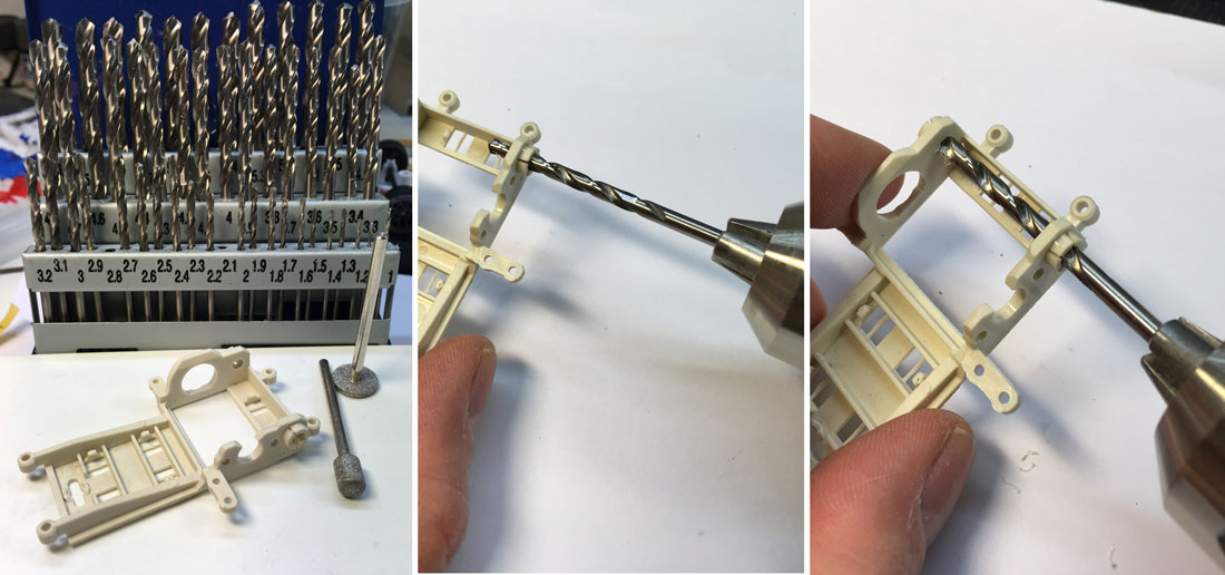
The procedure is actually very simple:
Start with the 3,3mm drill, use the slowest speed setting on your dril and let the drill bit "guide" itself through the rear axle hole towards
the one on the other side. As you repeat this process several times using a 0,1mm bigger drill every time..it does help to switch sides every two
or three passes.
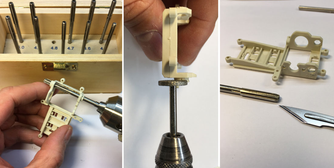
If you're into
fine precision tools, you can replace your drill for a reamer to enlarge the openings for the last 2/10th to 4,8mmø (the CH105 ballbearings are a
4,75mmø,
and if you source them from other brands..that's the diameter you'll be looking for) The next step is to grind away the outer part
of the olite holders.
You can grind them perfectly flat with the rest of the pod but I prefer to keep 0,1mm as it will be easier to align the
ballbearings later on.
Clean up any burr's left on the pod with the reamer or a sharp knife.
Room to move..and improve on fixed diameter gear
ratios
As I mentioned before, the lowest gear ratio with stock gears is 2.38 which means that on the longer
straights of some of the DiCSA events your Vmax will be limited.
If you want to run a lower ratio you'll be looking at different gears &
pinions with different dimensions.
So here's a number you should keep in mind: 24,5mm (6,5mmø pinion + 18,0mmø
gear)
This is not an exact value of the distance between the pinion and the gear (as there's an overlap etc etc) but its a good value to
compare possible other pinion and gear combinations.
For example the Slot.it 14t 7,0mmø Ergal pinion in combination with a Nylon Scaleauto 31t
17,5mmø Sw gear also adds up to 24,5mm. But with a lower ratio (2.24)
If you want to go lower, then you could use the 17,5mmø NSR gears,
although you will have to ream these to fit on the titanium axles. But you'll have ratios going down to 2.0 with a 28t gear.
Big pinions, small gears
With a 2.0 ratio you are approaching the limits on what a MX16 small can can accelerate and
decelerate on a 72-78gr Slotcar. But for the long Mulsanne straight a bit of extra top speed might give you that little edge.
For my cars I
prefer to use bigger nylon pinions and even when the sizes with your mixed brand pinion & gear combinations do match, your mesh might still be a bit
off.
So below are some images that can show you how you can give your pinion that little bit of wiggle room needed to adjust your mesh.
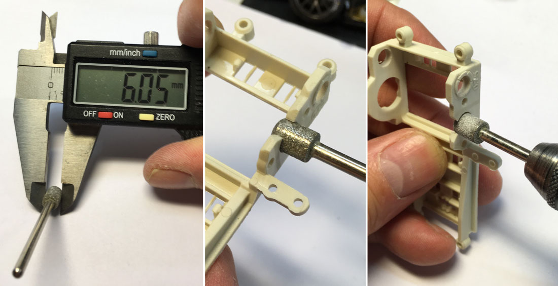
So what you'll be looking for is
grinding tool with a 6,0mmø, what you'll be needing to do is to enlarge the opening in the pod for the Motor bearing by 0,5mm forward and backwards.
Again use the slowest speed possible on your power tool to keep good control of where you're grinding material away.
The next step is to
enlarge the openings for the motor screws by the same amount. You can use a power tool, but a plain old fashioned rat-tail file will do the trick just
as well (just takes longer)
As you can see below I also grind away some material of the top of the pod, this is done to make it easier to snap
the motor in the pod..and reduces the amount you'll deform the pod by doing so.
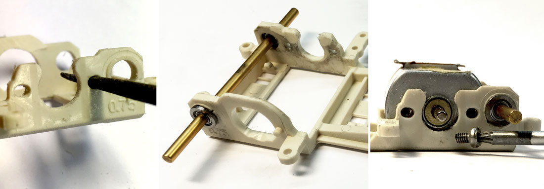
I usually wait with aligning the ballbearings
till after I've mounted the motor (as this will deform the pod a tiny bit) I use 2 short motor screws to secure the motor.
Best procedure is to
use the front screw to adjust the mesh (with axle and gear in place). Tighten it and then remove the gear to be able to insert and tighten the rear
screw.
The reason why I prefer to use Torqx screws should be obvious..they don't fall off your screwdriver that easily.
So there
you have it, with these mods you'll have an adjustable pod that accepts pinion/gear combinations within a 24 - 25mm range.
|
|
|

|
tamar
Posts: 804
Registered: 5-1-1989
Location: Gouda
Member Is Offline
Mood: A new beginning 
|
|
posted on 1-3-2019 at 12:10
|

|
|
Setting Gear mesh and axle play....for
Dummies
Sometimes when I re-read my posts I notice that I have omitted some of the basic steps in a described procedure...because...
...well, I assumed they were part of all slotter's basic steps. But that does not always seem to be the case. So...
To finish off my previous post on how to modify a Slot.it SW pod...here's one on an idiot proof way to set a proper gear mesh and axle
play.
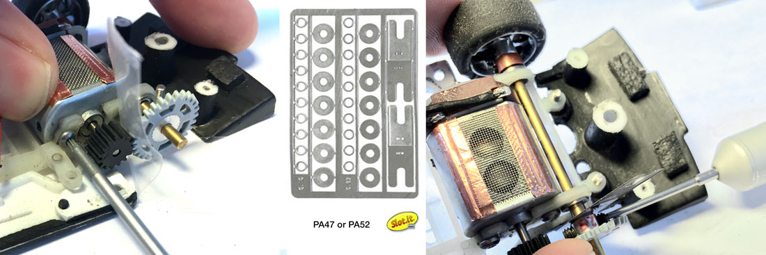
From left to right:
With motor, pinion, axle and gear mounted. Insert a piece of paper or a plastic zip bag between the pinion and gear.
Push the motor tight towards the rear axle/gear and tighten the front motor screw. Not fully, just enough to fix the motor position.
Remove gear and insert and tighten the rear motor screw (not pictured) and then the front motor screw
Get your axle play adjuster tool (the H-shaped parts) from the PA47 or PA52 slot.it axle spacer set.
Remount gear and insert tool between gear and spacer.
Squeeze/press gear tight on axle to eliminate any axle play.
Tighten gear grubscrew. If you use 2 grub screws tighten one side lightly to fix position of gear, rotate gear 180˚ tighten 2nd grub
lightly, rotate gear 180˚ tighten 1st grub more, etc etc.
Remove axle play tool.
So there you have it, an idiot proof procedure to set the same and correct amount of axle play and have a perfect gear mesh, any time, every time.
As usual the most simple ideas can be the most ingenious ones, and by adding the axle play tool to the PE spacer set a Slot.it PA47 and/or PA52 is
really one of the best buys you can make.
|
|
|

|
tamar
Posts: 804
Registered: 5-1-1989
Location: Gouda
Member Is Offline
Mood: A new beginning 
|
|
posted on 7-3-2019 at 09:15
|

|
|
The Road to Le Mans 1/32: 4 weeks and
counting
Just 30 days before the start of the first practice session in Henley in Arden. With the MK2 Sidewinder chassis now on the bench, work in the last
week was focussed on prepping the MK2 chassis and converting the MK1 chassis to a AW configuration. We've got a test session planned this Saturday
where the goal is to give both chassis a thorough endurance test and compare both configurations.
From prototype to production
With all the post on detail bits and pieces of the Ford, I thought it would be a good idea to post an overview of the chassis "development" from
the original ProSpeed chassis via the prototype Mk1 to the now almost ready for testing MK2 chassis. 3 images representing a lot off work done in the
past 3 weeks.
On the left the original ProSpeed design which more or less had the same shape as the Scalex Ford with the side skirts and diffuser attached to the
chassis.
In the middle the Mk1 prototype where I'd cut of the side skirts and diffuser and fabricated mounting points for the body support grubscrews and the
side suspension.
This is how we ran the Ford in the first two test runs.
On the right the assembled MK2 chassis the with all the lessons learned and changes that were made "manually" to the MK1 now incorporated in the 3DP
design.
The main difference being the addition of some reinforcement ribs on the chassis to prevent the chassis from bottoming out in the middle, a different
shape for the Flex slots in the chassis with the forward grub screws moved..forward. This was to make more room for the O2 chip.

The differences between the MK1 and MK2 are more visible from below. As you can see the MK2 chassis is a dedicated SW chassis, wrapped tight around
the the Slot.it pod.
Besides the shape of the pod surround you'll also notice that the rear of the chassis has now been beefed up and now has a U-profile in which we can
glue a kevlar strand for even more rigidity and crash resistance. Just behind the front axle is the mount for the front suspension bracket (which I
still need to fabricate) that will turn the quad point slot.it pod in to a tripod.
Last but not least, the guide has been moved forward by 1mm and the guide recess in the chassis has been enlarged so we can fit the Thunderslot guide
with its wider and longer guide saddle.

2nd time around
With the 2nd chassis almost ready to run it was time to start prepping a 2nd center body section. Wasn't to happy with the first one anyway, removed
too much material and the modifications were a bit crude. But you learn from your mistakes so I.m.o. the MK2 center body is much neater and
cleaner.
Although we could in theory run the modified plastic parts....I do hope there will be time enough to cast the MK2 body centre section in silicone and
laminate at least one GRP version.
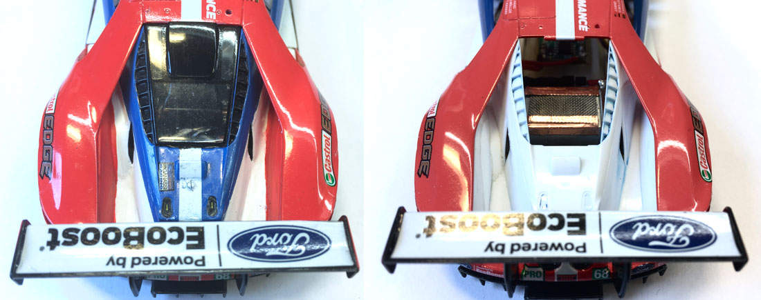
Spend a good few hours to get the motor wires, the ferrite man and the connector to the O2 chip in a position that works for both SW as AW
configuration..without interferring with the body. Here's a look "under the hood" as you can see it all fits, but its a tight fit wink.png

Pet project
Last but not least, a bit of scale detail. I needed to make a 2nd set of front wheels for the MK2 chassis, had a good look at the stock scalex front
wheels and they are actually pretty good.
A quick trueing on the hudy and they were as good as the Delrin Sloting plus wheels I usually use. But with one difference...
...the Scalex wheel has scale spokes, no hub and insert.
Modified some Black arrow brake disc which even when "lightly' coated with paint are not totally opaque and slid them over the wheel hub.
All we need to do now to create one of my long desired pet projects...is to stick a red smd led in the hub and we could have glowing brake disks.
wink.png
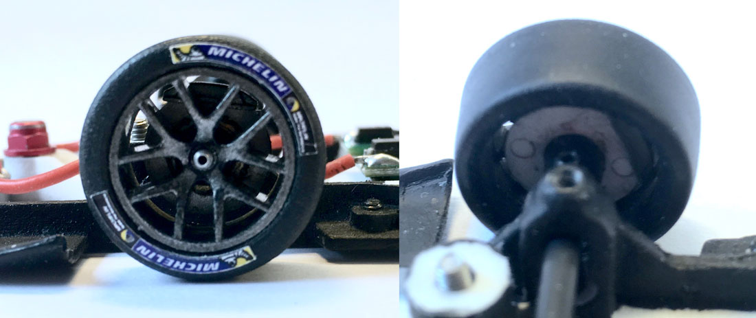
Testing 1,2,3
So there you have it, both Ford GT's side by side. Although the MK2 is a good step forward (at least that's what I hope saturday's test will
confirm) we'll most likely be racing a MK3 version in Henley with some minor detail changes and some extra 3DP bits & pieces.
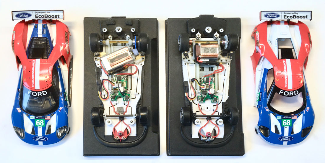
to be continued...
|
|
|

|
Big Al
Posts: 221
Registered: 4-6-2004
Member Is Offline
Mood: No Mood
|
|
posted on 11-3-2019 at 12:41
|

|
|

|
|
|

|
tamar
Posts: 804
Registered: 5-1-1989
Location: Gouda
Member Is Offline
Mood: A new beginning 
|
|
posted on 13-3-2019 at 01:55
|

|
|
The Road to Le Mans 1/32: 3 weeks and
counting
Just 24 days before the start of the first practice session in Henley in Arden. Looks like we're going to play catch up with Garage 27 for
car prep. We've had a good test session last weekend in which we managed to do a lot of work and testing, not everything I had hoped we could do,
but it was a very, very constructive day.
First and foremost, we've now got a good base set up for the new MK2 chassis, that may look easy, but with a new chassis you basically start from
scratch for 50%. And one those test days..time flies. But I'm getting ahead of the story, more on that part in a later post, because before we could
go testing I first had to finish some parts.
Bussy Bees and Lego
time..again
Marc was going to bring the Dental Vacform machine to Best (thx Eric) so we could pull some lightweight windows, meaning that I had to prep the
masters.
So here I go, its lego time again. Besides great for building the walls of your cast box, the little Lego pieces can also be used to support and
fixate the position of the part you want to copy.
Most important when they're fragile breakable parts like windows, even more important when those windows need to be fitted from the inside of the
body..to maintain the correct shape and fit.
On the left image you can see how I used some Lego blocks to build up a base. In the centre image you can see how I then applied the Modeling bees wax
around the Lego base. (sorry, a bit out of focus)
You can actually see the top of the Lego sticking out of the bee wax.
The Bee wax can be shaped cut and moulded with a knife, a spatula and even with your fingers. Its great stuff.
It gets softer when warm and can be dissolved (as in when you need to clean the master again) with cleaning petrol.
When building up the bee wax you need to pay attention to three things:
1 that you seal your master completely, because even with the tiniest small gap between the master and the wax...the silicone will creep in
between.
2 that you keep the master as pyramid shaped as possible.
3 that you maintain a clear definition on where your master ends, if needed you may need to go against the pyramid rule here, as long as the overhang
is minimal.
After bee waxing its time to build the cast box, and the to clean your master, and I mean clean, polish and remove every flint or dust particle that
you can find.
Because the silicone will copy anything, even the tiniest surface details like lettering on the window streamer or the tiny raised window frames that
Scalex tamponed on the glass...
...which in this case isn't such a bad thing... but that too is for a later post.
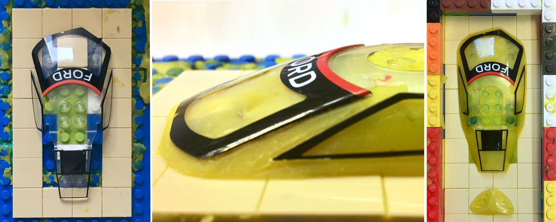
Casting bubbles and how to get rid of
them
I've covered casting the silicone before so I'll skip that part and head straight to the resin casting. Here (also due to time restraints) I used a
very fast setting PU resin.
Handy when you want to pour several casts in a couple of hours, but the down side of the fast stuff is... you've got a two minute window in which to
mix the stuff and pour it into the silicone.
As with silicone casting the main thing to avoid here are air bubbles, they are unavoidable (well with out a vacuum pot they are) but there is a
(quick) work around to get them out of the important parts...
.. and those would be detail parts like the thumbs and fingers of your driver or some delicate motor detail that took you hours to create on your
master, or the bottom (and thus in the mould the top side) of your air intake.

So before you start mixing your resin, have you silicone moulds laid out in sequence of casting, have a fair amount of kitchen towels ready for the
Oooops! :wacko: moments.
A spatula to wipe off the excess resin and most important..a couple of tooth picks.
Now you can mix your resin, make sure you mix the minimal amount, as the more resin you mix in the cup the shorter your cast window will be. Don't
worry about mixing too little for these type of masters.
Resin sticks to resin like....well that would automatically be corrected here on SF, but believe me it bonds very well. So even when your mould isn't
filled to the edge, just mix a bit more and complete the casting.
So..about the work around to get the worst bubbles out...well its simple, as you can see in the pics above I use the tooth pick to pry them out of the
deep parts in the mould.
Just stick it in the cast resin while its setting and wobble it around... sounds simple doesn't it ?...
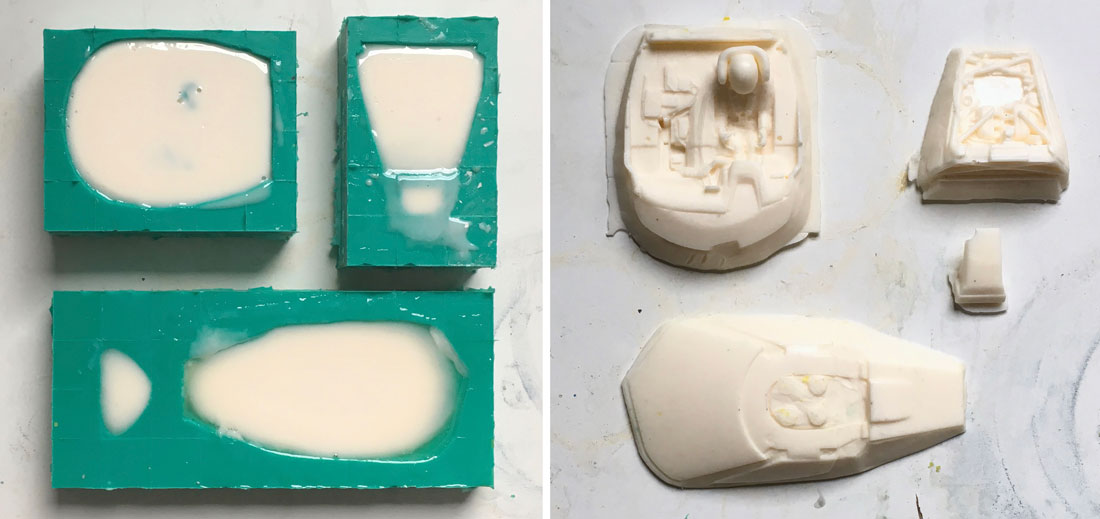
...well off course it isn't that simple and it will take you several casts before you get it right as can be seen in the picture above right.
Took me several pours to get one air intake without some air bubble caught in the mould. But the windows and headlight lenses came out perfectly.
Ready for some Saturday afternoon vacforming.
Front suspension from quad pod to
tripod
There was one more item that I had to fabricate for the MK2 chassis and that was a bracket to mate the Slot.it SW pod to the central front suspension
mount we'd incorporated in the MK2 design.
We'd used a similar design last year with the C7R for which Stefan Kievit designed a nice 3DP part, but although it worked very well, that bracket
needed to be dis mounted from the motor pod if you wanted to change the O2 chip.
For the Ford I wanted too keep it more simple, stronger and lighter. So I rumbled through my supply of GRP and cut this small (and if I may say
elegant) bracket from a 1mm thick sheet.
A Big head tall Slot.it suspension screw, some spacers and a 2mm bushing, a short Scaleauto spring and a Thunderslot top nut.
The Slot.it SW motor mount had now been modified from a quad pod to a tripod with just on screw to set the front pod float, which can be done without
taking the body off.
Now we were ready for some serious test runs.
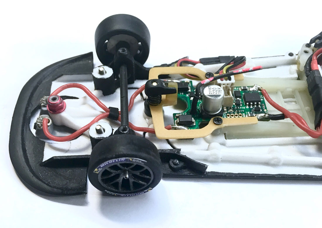
To be continued
p.s. Hi Al good to see you back here..wie het kleine niet eert 
|
|
|

|
tamar
Posts: 804
Registered: 5-1-1989
Location: Gouda
Member Is Offline
Mood: A new beginning 
|
|
posted on 14-3-2019 at 22:41
|

|
|
The Road to Le Mans 1/32: 3 weeks, some Team
news-updates
In just 21 days we should be arranging all the tables, chairs and the Marshalling floor mats @ Warwick college sports hall in Henley in
Arden.
With all the time and effort it takes to set up the 1/32nd DiSCA La Sarthe track a helping hand is always appreciated.
Alex and Gary have a place for every bit of track and scenery firmly locked up in heads...(a couple of thousand items, but they do have a written
manual to fall back on)...so we'll just be taking the dumb and heavy work of their hands. 
Took a few nights off working on the Ford's, also needed time to catch up on posts, pm's, emails etc etc. One of them lead to a very interesting
bit of team news
Scalextric detail parts...
As I mentioned before the Scalex Ford is a very nice and detailed car with some nifty design features to prevent breakages in case of a crash
(well..with exception of the aerials)
Before I start my builds I usually dismount all of them and store them safely in a box for later mounting or to use them to create masters for rubber
casting or vacforming.
To be honest I had a very hard time trying to get the mirrors off the body (as I wanted to recast them in rubber) noticed that they were quite
flexible and upon closer inspection found them to be cast...in rubber!
Now that was a big time saver and it's a real pain in the "buttocks" to paint rubber nicely, so here a feather in your cap, way to go
Scaley.:thumbsup:

For most of you that have acquired a Ford one of your concerns might be how to keep that delicate rear wing sticking way out the back, on your car..in
a crash...
Well you shouldn't ! You should allow it to come off..at least in a hard crash.
The rear wing has been designed as such that it clips into a mount and would come off in a hard crash..if not for a tiny drop of glue added in
China.
But that tiny drop of glue actually prevents the wing supports to come free in a hard crash and may result in breakage.
So stick a thin scalpel next to the supports into the wing mount and wiggle to cut the glue and you're home free...but there's more.
Once you have the wing off the car and flip it upside down you'll notice a seam line and that its actually cast in two parts: the rearwing supports
and the top wing with the endplates.
So again, take out you thin scalpel blade and carefully, and I do mean carefully (as in always point the sharp end of the blade away from you) try to
pry it between the wing supports and the wing.
Now on two of the three wings I have treated this way there were only small dabs of glue used to fix the support. I could easily pry the blade between
them in the middel and wiggle my way with the scalpel to the sides and the wing would come off.
But with one wing someone in China had been really thorough and more generous with the glue, couldn't get the blade in between.
In that case I would advise you to leave it as it is and "just" be content with the "clip in" safety. But if you can separate the wing from the
support and clean the recess from glue.
Just a tiny bit of thin double sided tape or a small dab of shoe goo will give you an added safety feature to prevent breakage in case of a serious
crash.
...and Scalextric after sales
service
Ok so back to that PM I had send, the one leading to a nice bit of team news. DiSCA sporting rules require all detail parts to be present on the
cars.
Small detail parts (like mirrors and wipers) only need to be present at the start, but wings need to be present at all times.
Should they come off you'll get a notification from Race control and you'll need to Pit within 5 laps to replace it.
Which (if your car is prepped for it) should not be a problem as by that time..a Marshall will kindly have placed the part in the "lost & found" bin
at RC.
And if the Marshall is bit a slow, you mount the spare and place the retrieved item in your spare parts box in the Parc Fermé... later.
This procedure works well in the day time...but in the night darkness.... it may take a lot longer before the "lost" wing is retrieved...and some
are "lost" ...forever.
So it is handy if you have at least 3 or 4 spares.
So Tuesday evening I send a PM to the only Scalextric rep I know, well at least I knew he is a SF member. I modestly asked if he could maybe act as
a liaison...
... and ask Scalextric if they would be willing to "support" our effort with 2 or 3 spare wings and mirrors.
Got a PM back the next morning with a reply that Scalex really doesn't have any facility to supply spares. But, to drop him an email with my contact
details...
...and he would dig round the office and to see if they had any spare shells etc. etc.
In the afternoon I got an email that he [/size]couldn't source any spare shells, but that 3 complete cars were now laying wrapped and ready to be
shipped out in the post room.
Way to go Scalextric, that's what I call "after sales service" You ask for 3 wings and mirrors and you get 3 complete cars, it was
like Christmas all over again.
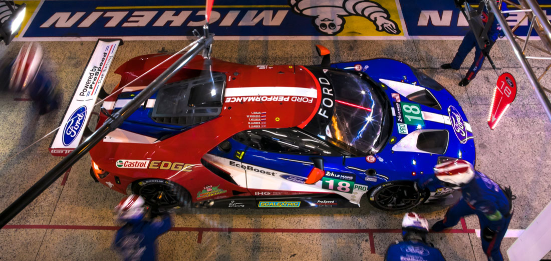
So as a thank you the Ford MonkeyTown Team NL cars will now proudly carry Scalextric decals on their bodywork. :thumbsup:
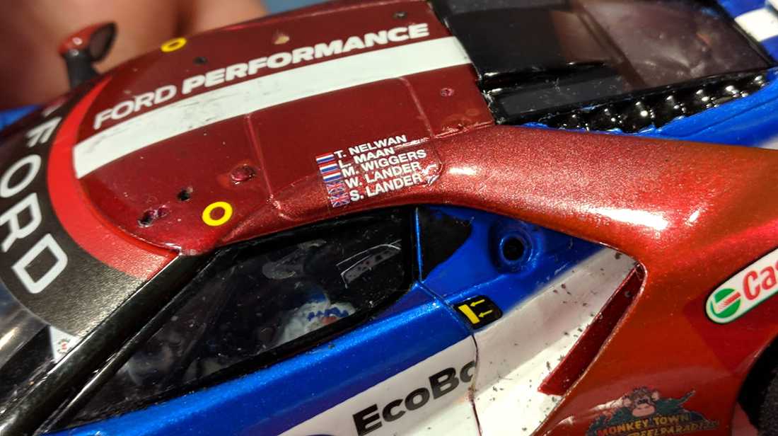
And while we're talking decals, here's an other Team update: on the roof we'll also have decals with the names of Wayne and Stephen Lander listed
as drivers of the #18 car.
Regardless of how Brexit will end..here's to another Anglo-Dutch cooperation :cheers:
To be continued
|
|
|

|
tamar
Posts: 804
Registered: 5-1-1989
Location: Gouda
Member Is Offline
Mood: A new beginning 
|
|
posted on 18-3-2019 at 08:44
|

|
|
Spotting the tales of Tail-end Charly
So with me taking a bit of time off watching motorsport, not much work has been done on the car this week, but..there's plenty of stuff I have not
posted yet. One of the things I'd thought at least someone to notice, was the work done at back of the car. I mean there were more than enough hints
in some of the pictures I posted. But apparently nobody dared to ask what I had really done to my Tail end Charly...the huge diffuser sticking out the
back of the Ford.
Ever since the ACO/FIA/IMSA aero rules changed a couple of years ago diffusers, almost bigger than those seen on LMP's have become a trade mark on
the GTE/GT-LM class cars.
And as such they've started to appear on slot-car models. Not that much of a problem on a stock chassis, but as we learned with the BMW M6 ....they
can get you into trouble on a podded chassis with lots of suspension travel.
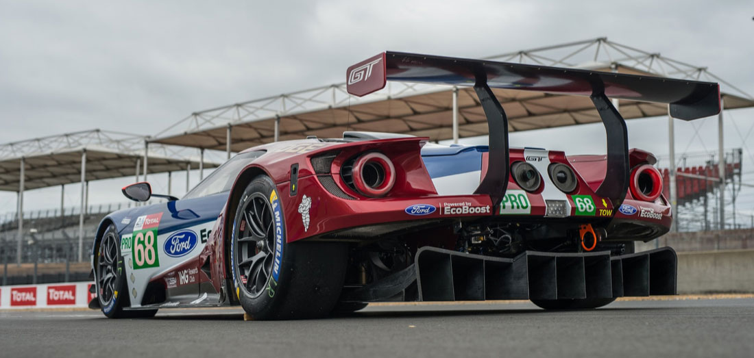
The wishbone's connected to the collar bone, the collarbone is
connected to?
On a podded chassis with suspension, you max amount of suspension travel should ideally be smaller than the ground clearance your running. Other wise
you chassis will rubb the track. No matter how long your screws are or how tall you springs are...your looking at 1-1,5 mm of travel max. But as the
back of the chassis sticks out behind your suspension mounts...a small the amount of travel at the suspension mounts will be translated in to a bigger
movement at the back. Meaning that if a lot of chassis is sticking out at the tail end...like on the Ford...it will be rubbing the track way before
you get near 1,0mm of travel.
So somewhere in early februari, I'm working on the chassis side suspension, fiddling with the motor-pod, mounting it to the chassis for the umpteenth
time. To keep the pod in the correct position for me to drill the holes for the suspension screws, I fully tightened the rear pod screws.....and then
it hit me! With the pod now firmly connected to the chassis and the rear diffuser behind it... no movement between the two parts, the diffuser was
just as much connected to the pod. What if.....

So at the end of first shakedown on Sunday feb 10th there was one more test we needed to do. The "What if" I wanted to test was how the handling of
the chassis would be influenced...if the diffuser was not connected to the chassis but mounted directly to the motorpod.
As this would be a "no way back" kind of test, we first tested if the handling of the car became worse with the rear pod screws not connected to the
chassis at all. The handling of the car remained the same...all we needed to do was ad some extra spacers inside the springs to limit the suspension
travel. Ok ..so far so good, next step.
Now it was time to cut the back of the chassis off and mount it fixed to the motorpod. Immediately we noticed that even with the full amount of
suspension travel the diffuser was no longer rubbing the track.
Yeeeeeeeeeeehaaa 
With a big smile I added the pod mounted diffuser to the number of modifications to be discussed the next day with Stefan Nalbach to be incorporated
in the MK2 chassis design.

On the left the diffuser cut of the prototype MK1 chassis here the diffuser was still
mounted with screws from the bottom, on the right the MK2 version with the top mounted screws. Rubber washers were added for e bit off extra
flexibility in case of a hard hit to the rear of the car.
to be continued
|
|
|

|
tamar
Posts: 804
Registered: 5-1-1989
Location: Gouda
Member Is Offline
Mood: A new beginning 
|
|
posted on 6-6-2021 at 11:30
|

|
|
The Road to Le Mans 1/32: 5 days and counting
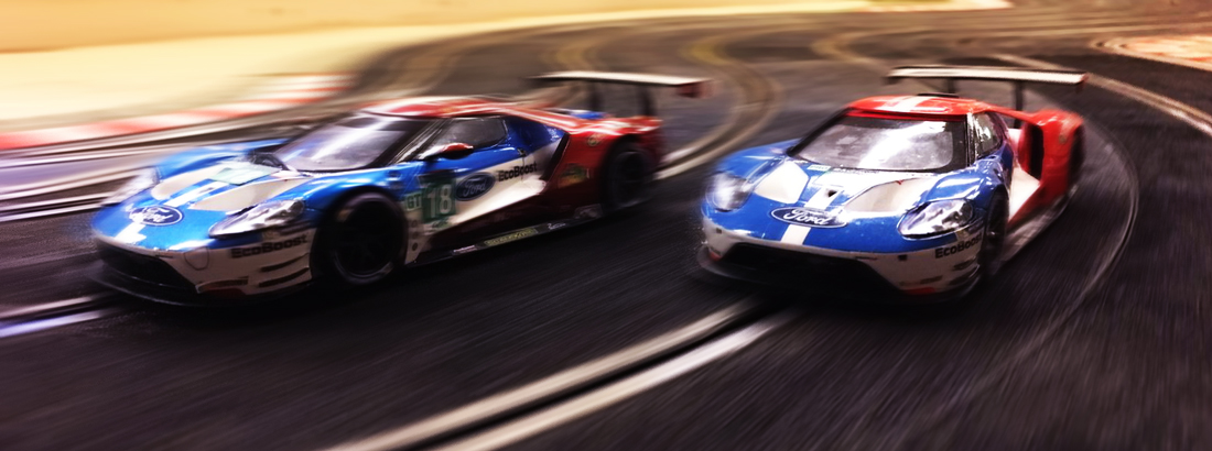
Yesterday we had an 8 hr marathon session in Best. Not that we drove for 8hrs..unfortunately no. The 3 Dutchies (Lennard, Marc & yourstruely) started
work @ 14:30 to get the
Mk2-A 2018 Ford ready for its first shakedown. 19,5 man hours later (6,5hrs x 3= 19,5 hrs in total) the 2018 liveried car ran its first laps alongside
the 2017 MK2 Ford on the Suzuka track.
And here's were all the testing, development and preparations of the past 8 week payed off. The MK2-A was stable, smooth and fast straight out of the
"box".
So we now have two set-up's to choose from: the Mk2 2017 car with a 1mm offset and the Mk2-A 2018 car with a 0,75 offset.
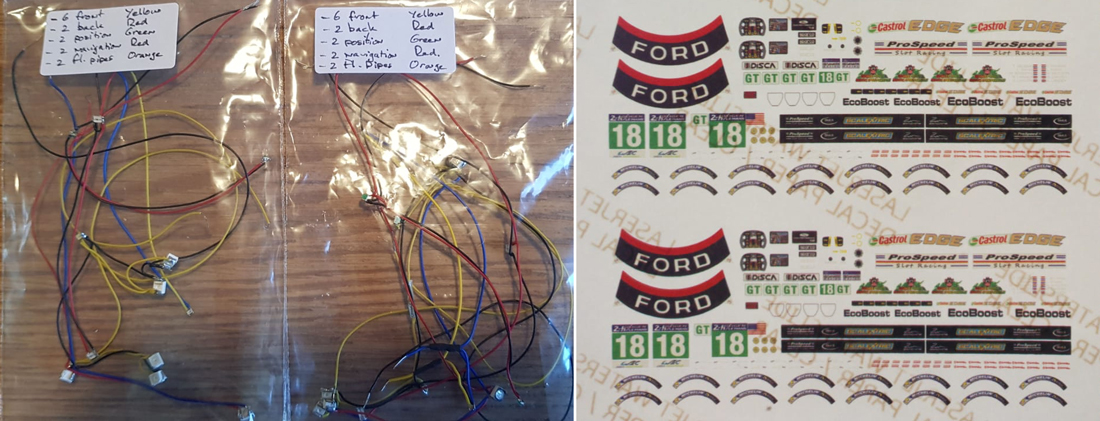
Does that mean that both cars are finished...No, bodies need to be reinforced. Got some minor paint touch ups to do and the SMD led lights still need
to be installed in the bodies
The latter is most likely to become a Friday morning job, and you can expect us to add the last decals on Saturday... just before concourse 
But we've made serious progress yesterday, so I confident that we'll be able to hit the ground running when the track opens @ Henley on Friday
12:30
to be continued
|
|
|

|
tamar
Posts: 804
Registered: 5-1-1989
Location: Gouda
Member Is Offline
Mood: A new beginning 
|
|
posted on 6-6-2021 at 11:45
|

|
|
The Road to Le Mans 1/32: 360 days and counting
After we arrived at Le Mans the race it self did not proceed as good as we were aiming for I am afraid.
I blew the light installation on the 2018 racebody Friday evening just before the start of qualifying, so that had to be redone on Saturday morning
06:00 hrs.
Then we failed post qualifying tech (rear axle too wide) which meant we ended up in Siberia rostrum wise.
We'd also been chasing a weird package drop problem which ruined most of our free practice sessions and persisted till finally solved by Maurizio
after 1 hour of running in the race.
After swapping chassis, chips, ID's, firmware and controllers, faulty cartridges on both our prime and spare controller were finally diagnosed as the
root problem.
We got a new one from Maurizio and from then on the Ford finally started to live up to its potential, but on set-up and fine tuning we were running a
day behind so we had to do that during the race.
We sorted what we could and slowly but steadily started making good progress, climbing up from dead last to 7th overall...
...but dropped back to 9th overall after a string of pitstops trying to solve what looked like a loss of power problem but in the end turned out to be
a binding front axle.
The good things were that with the front axle sorted the car ran faster than ever and Lennard posted our fastest lap time of the race with a
14.96...
...on a track that was definitely a good 2 -3 tenths slower than at the start of the race.
And that all the development bits and pieces that were on the car performed as predicted and both chassis and body survived the 24hrs nearly scratch
free.
We lost a mirror, one wiper and a sideskirt.
Last but not least, our cooperation as a mixed Anglo/ Dutch team worked really well, by working as a team we managed to solve most of the problems
that the event threw at us.
There's still plenty of development room left in the Ford..so we'll most likely run it again in the other DiSCA WEC events planned for this year.
That will hopefully sooth the pain of having to wait for 360 days before we can head up the road to Le Mans... again.
With kind regards
Tamar
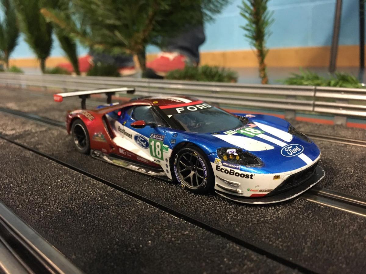
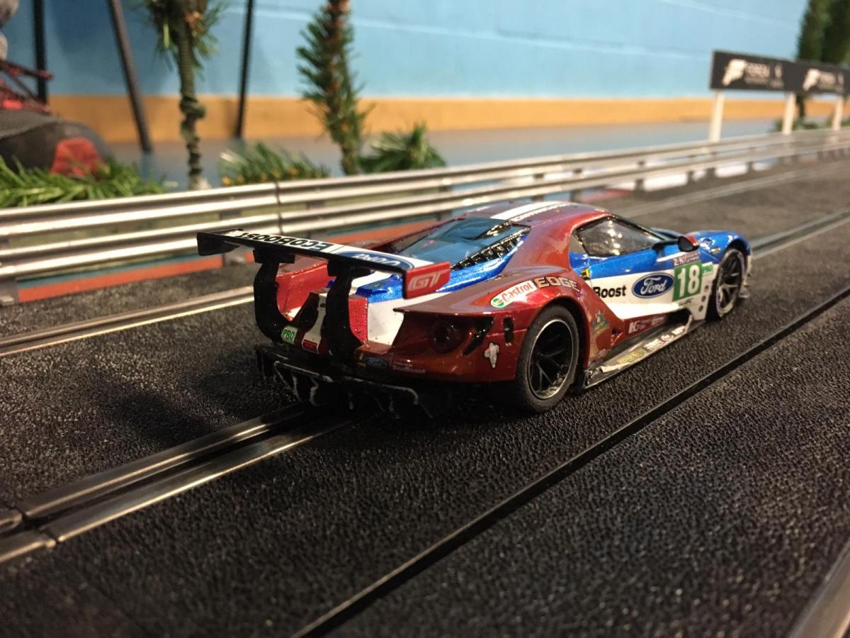
Post race pictures, the Ford finishing the race on the Mulsanne Straight.
|
|
|

|
tamar
Posts: 804
Registered: 5-1-1989
Location: Gouda
Member Is Offline
Mood: A new beginning 
|
|
posted on 6-6-2021 at 11:51
|

|
|
The Road to Le Mans 1/32: 240 days and counting
Hello Guys, its been more than 4 months since my last post on the Ford GTE, in that time we've been on the Road to Rockingham and are now preparing
for the Road to Barcelona.
(well actualy Igualada but nobody has heard of that place) So...time for an update. To be honest the Ford had been negelected a bit during those
months.
After the intensity with which I had been building slot cars from January till April, I needed a break... and when I did get back into the groove,
some new projects required my attention.
So I just reread my last post LM post to see where I had left this topic and which topics I did get to post: " ...We lost a mirror, one wiper and a
sideskirt..."
Funny how one tends to remember good things and bad things immediately shift to the background. Cause in all honesty we lost a bit more than that
Best laid plans...
Here's one of the things I did not get to post during our road to Le Mans: Obviously the achilles heel of the Ford GTE was going to be that big rear
wing sticking out the back.
So one of the first things I did during the build was to add small blocks of foam rubber in the rear of the body to create a flexible structure to
mount the rear wing supports.
I simply cut a slit in the top of the foam so the wing supports would slide in. Over time however the wing supports started to cut through the foam
(see picture left).
So I reinforced the bottom of the foam with some thin sheet plastic (see centre pictures).
This set up worked very well during all our test runs, the foam was tight enough to keep the rear wing fin place while driving, allowed for some
flexibility during crashes...
...and should the wing come off..it was very easy to slide it back in...or replace it with one of the spares we got from Scalextric. Or so at least
that was the plan.

..and then just winging it
Well the plan did not work entirely to our satisfaction. During the first hour of practice a Marshall that wasn't paying attention to oncoming
traffic, ripped the first wing off as he lowered a car on the track...right on top of ours.
Unfortunately this would happen many more times during the weekend. Sometimes the wing would come clean off and then it was a simple remount.
Sometimes the top wing would be ripped from the supports and in a few cases the wing supports themselves would break.
Even with what I thought would be an ample supply of spare rear wings, Wayne and Stephen spend quite some time repairing wings during the 24hr event.
Rock Bull Rubber
So while giving the Ford some much needed TLC in preparation for the Rockingham WEC event, finding a better solution to prevent the wing being ripped
off was high on the priority list.
I gave casting the wing supports in rubber a try, but could not get the thick rubber mix to flow into the mould cavities so in the end I used the same
solution as on the GT3 Bentley.
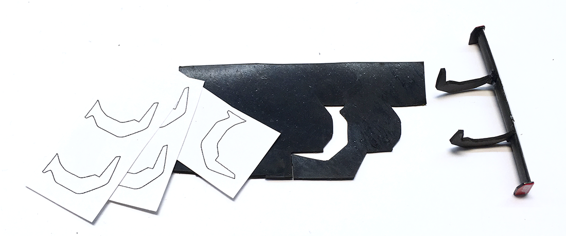
Drawing a template of the wing supports, printed them on label sticker paper, stuck the label on some NBR 1mm thick rubber and cut the rubber with a
sharp X-acto knive.
Filed two slots in the bottom of the rear wing and used a drop of Zapp medium thick superglue to secure the supports to the wing and a small drop at
the base of the support where the enter the body.
The result, a fully flexible mounted wing. As a added security I put some shoe goo (neoprene glue) over the top connection so that even if the
superglue would fail..the more flexible shoe goo would keep the wing in place.
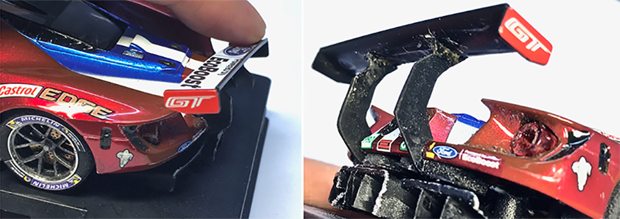
Worked like a dream, did the whole Saturday practice and 6hrs Sunday race with the same wing. And although the car came of several times..the wing did
not 
For those that would like to modify their Scalex rear wings in a similar way. Attached to this post is a PDF with some wing support templates.
For the 1mm NBR rubber try you local industrial rubber supplier. A few quid will get you more rubber then you'll need for a lifetime.
With kind regards
Tamar
Attachment: Ford-GTLM_wing-supports.pdf (168.49kb)
This file has been downloaded 443 times
|
|
|

|
tamar
Posts: 804
Registered: 5-1-1989
Location: Gouda
Member Is Offline
Mood: A new beginning 
|
|
posted on 6-6-2021 at 15:22
|

|
|
Vacformed clear parts...
Some love, some hate them. Main reason racers use them is to reduce weight high up in the body, although I'd say the added flexibility they
give the body is just as important. And with Ford not having that much "high" in the body, for this car the most important reason.
So its a performance part..but that does not mean you can't make them look good.
I.m.o a badly executed set of vacformed windows can totally ruin the look of a car. Unfortunately not an uncommon sight on "performance slotcars.
Clear windows, no window frame, no window streamer, the Dutch have a nice word for it "Blote billen gezicht" Google it, you'll have a
laugh.
Ok let us dail back the clock to somewhere mid March when Marc brought his Vacform machine to the club and used the bucks I'd perpared to pull a
couple of windows and headlight lenses.
The copies were perfectly clear and had good shape definition, but...when we cut some of them and did a test fit...
...the big one piece front and rear window was too big, it would not fit inside the body.
I knew this was going to happen, because the buck I'd cast was an exact copy of the Original Scalex window.
For Vacforming the most used material is 0,2 mm thick PET sheet. During the vacforming process the sheet is drawn over the buck.
As a result of the material thickness the size of your Vacformed copy will be bigger than the original.
There are ways to make exact sized vacformed copies... but there was just no time to make a second positive silicone cast and pour a negative buck.
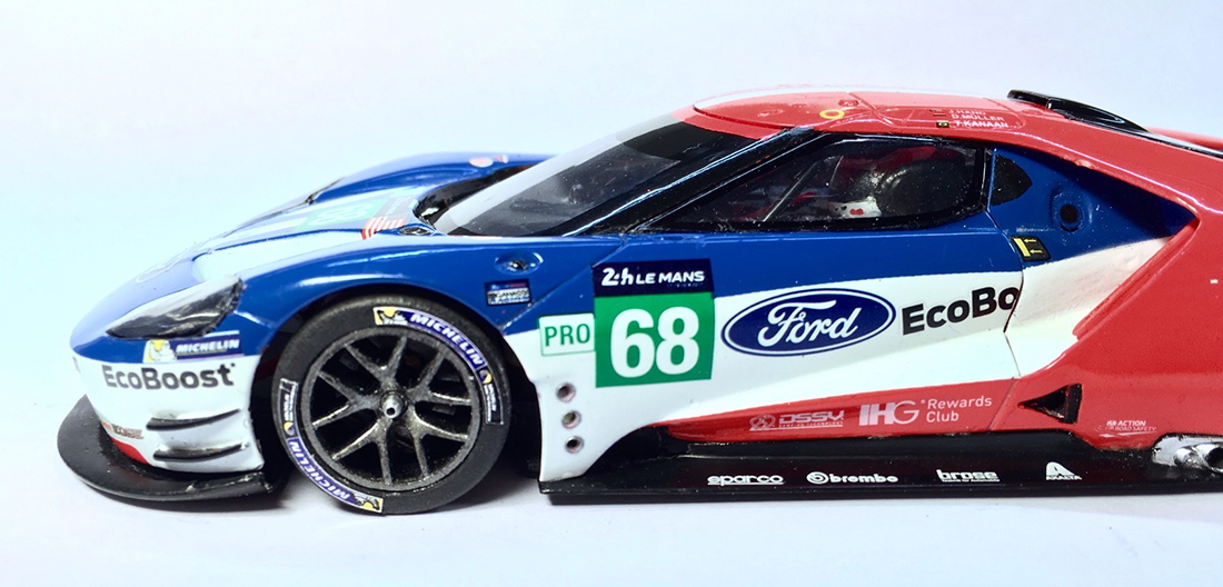
In this case it wasn't such a problem as all I had to do to make the windows fit was to cut the front and rear window loose and mount them seperately
in the body.
There was still a small gap at the rear of the side windows, but at the time I could live with that.
...how to trim and detail them...
The hardest thing with cutting clear parts is to see where exactly you need to cut (even with my reading glasses) because they are..clear parts.
Depending on the quality of the vacformed part finding the edges can be difficult.
So here's a tip: use a fine steadler (waterproof) feltpen, and outline the parts before you cut them. Here's how you do that.
Flip the vacformed part so the inside is facing up. Stick the tip of the pen in one of the corners push the tip to the outside wall and gently trace
the outline.
Don't worry if you make a mistake or your pen slips, it happens, even to me. Just wait a bit for the marker ink to dry and use a toothpick to
(carefully) scratch away any excess ink.
vacform_tracing-outline.jpg
Tracing the oulines before you cut the clear parts makes life a lot easier as you'll have a better guide where to cut.
To make the cut I use a pair of small curved and straight scissors to cut out the rough shape. Then its a repetition of test fitting and trimming the
part to get that perfect fit.
For the fine trimming of the edges I don't use the scissors but a small sanding block/stick. Allows for much fine adjustments and gives a nice and
smooth edge.
The window frames on the side and rear window were lined on the inside with the same fine steadler felt pen.
Remember how I mentioned in that earlier post how the silicone would copy anything, even the tiniest surface details like lettering on the window
streamer or the tiny raised window frames?
Well these sure helped here as I could use the small edges as a guide to ink the window frames.
So a thin marker for the outlines and then I used a broader pen to fill in the whole inside. You might have to do several passes with the marker for
larger areas like the air intake.
Cherry on the cake were the decals I made for the window streamer .
 . .
..and how to mount them
So now you have you vacformed clear parts trimmed, detailed and ready to mount. As I mentioned before adding more flexibility to the slot body was the
main reason to do them.
So for that reason I prefer to not to glue them rock solid with glue, but mount them with as much flexibility as possible. In most cases that means
(double sided) tape.
For most GT's the tape will be covered by the window frame(s). In general I add full width tape to the top of the windows and just small tabs to the
sides and bottom.
When its time to firmly secure the clear parts for a race I usually add a bit of UHU Schnellfest to the corners.
It is a two component glue that remains a bit flexible and dries totally clear.
From what I've heard its similar to the GS Hypo glue some UK members like to use.
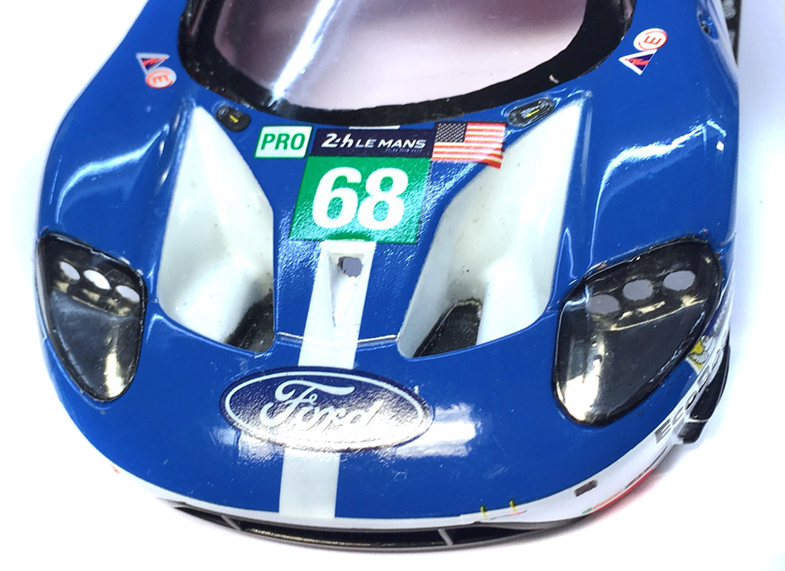
But sometimes your clear parts have very thin window frames or like the headlight lenses, none at all. Here's where I use a black 1,0 mm wide and 0,2
mm thick doubble sided tape from 3M.
Altough tape isn't the right word, its more like mini window kit on a roll. Not surprisingly as its main use is to glue LCD screens to smartphones.
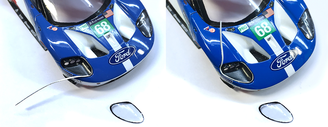
Simply mount the tape to the edges of the headlights and press it firmly in place with the backside of a brush or a toothpick.
Once you've removed the backing paper all that is left is a thin black edge that resembles scale window kit. Then press the part in place on top of
the tape.
It is the only black colored tape that is strong yet flexible enough to mount clear parts on a slotcar body. As it vulcanizes the longer it stays on
the stronger the bond gets. And it looks amazing.
Here is a link to a Dutch Webshop that sells the tape, but you should also be able to source it from your local mobile phone repair shop.
Ok that's it for now, one more backlogged post sorted...more to follow
With kind regards
Tamar
|
|
|

|
tamar
Posts: 804
Registered: 5-1-1989
Location: Gouda
Member Is Offline
Mood: A new beginning 
|
|
posted on 6-6-2021 at 15:42
|

|
|
The Road to Le Mans 1/32: what a trip it has been
Almost done with my backlog posts on the Ford GT LM, I must say, looking back to this topic, wow I really went all the way with this little
racecar.
And as in live, the road travelled was almost more rewarding and interesting than arriving at our destination.
Because what was initially a simple Plan B to get us to Le Mans, quickly grew into something much more complicated.
The challenges this little Ford raised have tought me a lot, the lessons learned already being applied in new projects.
But now after 6,5 months, 8 pages full of post, almost 10.000 views, it is time round things up and bring this project to a close.
I must say, posting and building at the same time did cause this thread to swerve off topic from time to time and had me skipping from one topic to
another.
So this one...with a bit off hindsight, can be considered as the Ford GT LM epilogue.

Ford GT LM...body double
For our trip to Le Mans two complete Ford's were build, one would serve as a test mule and was destined to do most of the free practice running the
other would be kept clean and fresh for the 24hrs race.
We ran one car in the 2017 livery and one in the "special edition" 2018 livery courtesy of Hornby Hobbies. So wha t was so special about the 2018
car?
Well, when I talked to Simon about our plans to do the 2018 car...if we had the time. He mentioned that he might have one for us laying around.
Its was a dis-approved pre-production sample with a minor discoloration error. I could have it under one condition: That I would not sell it after the
race!
(apparently like a misprint on a stamp this tends to make such an item rather unique and increase its value somewhat)
Well Simon, rest assured, this little Ford will never leave my possession, as a matter of fact I might pick up a second 2018 car when they will be
released 4th quarter 2019.
Because the metallic color of the car is just stunning.
As you can see on the picture right. I did some paint tests as I needed to touch up the paintwork on some of the areas where I'd modified the body
work.
In the end I decanted some Tamiya TS 39 & TS 95, mixed 1:1 and applied it with an airbrush.

Lights: Short circuit and short cuts
One of the things I never got to post prior to the race, the lights. Main reason of course was that we still needed to mount them as we left for the
UK on Friday.
Me shorting out the light chip on Friday evening just before the first qualifying session didn't help. Luckily we had the body double which, with a
very rudimentary light set,
allowed Wayne and Stephen to do some night running. Z-machine had send us an ample supply of spare light sets, so the alarmclock was set for 05:30 on
race day, first job
was to start repairing the lights of the race body.
Funny how time flies when you most need it, in order to get the car finished in time for the start of Saturday morning 2nd Qualification session we
would need to make some (short) cuts.
With the Ford sporting 8 leds at the front and no time to properly trim the wiring, using the stock wires would add another 1,5 - 2 gr to the body.
But as I went through my spare box I found a spare light set Fola had made for the Toyota TS040 we raced in 2015.
The headlights of the Toyota had 3 tiny round smd leds and one square on each side and they were mounted on very thin laquered armature wire.....and
guest what...
..not only were they a perfect fit for the Ford's headlights, they were also much lighter.
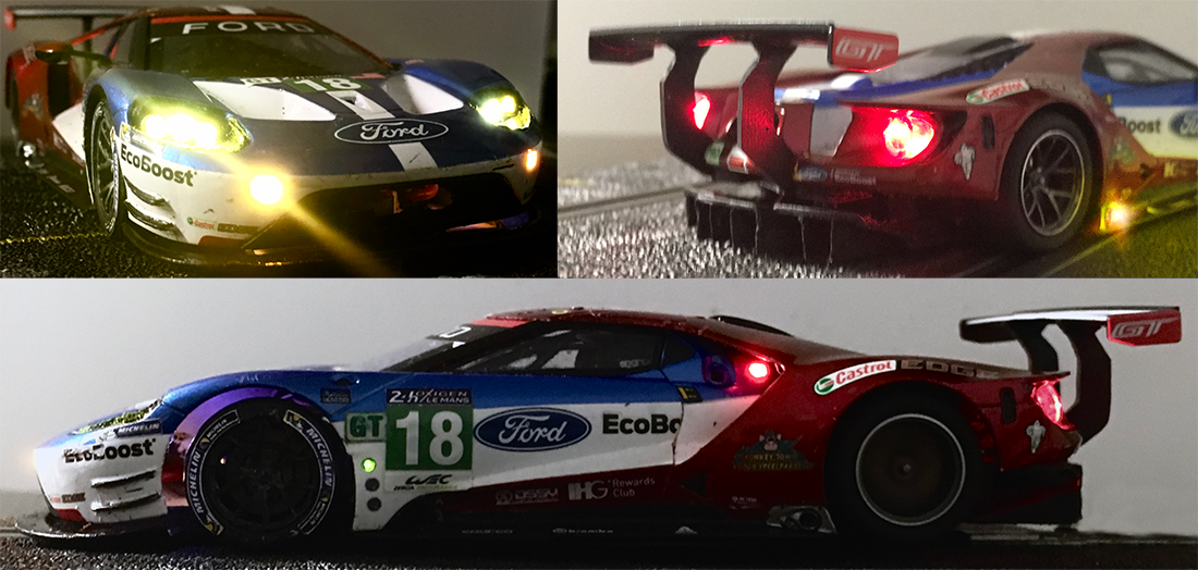
Lights: Friend or Foe
Where on a race car the lights are there for the racer to be able to see the track, on a slot car the lights are there for the racer to be able to
see...his car.
And believe me on a digital track as big as the 1/32nd La Sarthe...that can be a harder job than you may think. Running in a pack going into the esses
or rounding Mulsanne corner...
...every bit of extra light that will help you to identify which car in that cluster of lights belongs to you...really makes a difference.
With the distinctive triple headlights and two fog lights, we had the front covered. The sides...hmmmm not so, ok those extra identification lights
behind the cockpit...
...we did not want them to be as bright as the neon light Ditslot had done the previous year. But due to the short cuts we had to make repairing, all
the side lights were a bit dim.
We also ran with the flaming exhaust led on the right side as this was the visible side and helped you spot your brake point on the Mulsanne
Straight.
where the car lacked identification most was at the rear. Sure the Ford's taillights were pretty big, but they shone just as bright as all other
cars.
An extra identification light at the rear would have helped here...something on the wishlist for next year... as are the glowing brake discs.
More diffuser follies...
Here are some more diffuser follies I dug up from my image folder. I'd almost forgotten about this one, and that while it was one of few occasions
where I've been able to add scale detail...
...and improve the performance of a car in one go. So what are you looking at? Well, after our first test runs with the diffuser attached to the motor
pod one of the team members wondered:
Wouldn't the added mass behind the real axle be ditrimental to the un sprung weight and performance of the car?
My initial reply was that on all the SW- short can cars we'd raced so far, the best set up had a bit of weight under the rear axle....but ok...
let's see if we can make the diffuser lighter.
So I cut off the 0,7mm thick diffuser strakes and replaced them with very thin plastic cut from a booklet cover.
And behold even though it was but a 0,6 gr weight gain on a 2,5 gr diffuser..it did make a small difference...the cars was 0,05 sec faster... and it
definitely looked much better...
..and as the strakes were now flexible...it improved the crash resistance as well. Absolutely loved it...but the time...and effort. You can understand
why I modified only one diffuser like this.

Ford GT LM Set-up : Control and adjustability of chassis, pod and body movement.
Ok, enough talk about detail stuff, time to get down to the nuts and bolts of the car. Here's some more info on the technical side and the choices we
made on the Ford's set-up.
Some slotracers look at a car and see the chassis as the part that makes the car go, and the body...well it needs to have a body right? But its mainly
considered as dead weight.
So let's get rid of that dead weight as much as possible...right? True a lot of time and effort has been made on the Ford bodies to make them light,
not as light as possible but very close to the minimum.
But even if you do get down to the DiSCA min. 19,5 gram, that's not dead weight sitting idle on top of your chassis. That's weight you can use to
make the chassis work...even better.
Take most 1/32nd slot cars out of their box and you''ll have a car were chassis, pod and body are screwed tightly together as one. As such any
movement of the car will be transferred to all parts.
If the car leans in a corner it will do so as a whole, if the car rides a bump in the track it will do so as a whole. etc etc. On a plastic track,
specifically a Ninco track..that's no good.
In an optimum situation you would want all parts to be able to move independently and at the same time be able to control their movements and
interaction independently.
Alas in most cases you'll have to settle for a compromise.
So first thing most will do is give the car some body and pod float, dump the horrible wood screws that will scrape inside the screw holders for a
good set of half shaft metric ones...
...and your 3 components (body chassis & pod) can move independently. Loosen the body screws a few turns and you'll be able to control the amount of
float, at least..upwards.
Where the body will rest on the chassis is often a different matter. Plastic tends to warp and bend as it gets loaded, some start to do so from the
factory.
A lot of slot cars are designed in such a way that the body will rest on the chassis side skirts and front splitter. As such they will transfer the
body weight to the chassis everywhere...
..and in most cases...no where in particular.
Body Supports
I prefer to have the body transfer its weight to the chassis on 4 points only. To have those points spread as wide apart between the axles and as
close to the axles as possible.
So if on the stock car the body rests on the side skirts (as with the Ford) I will cut those off and glue them to the body. As such new body supports
will have to be fabricated.
These are easy to make, just cut some pieces of think plastic rod or L shape, glue them in the body and cut them to the right size. Which is basically
what I did Ford the first Ford prototype chassis.
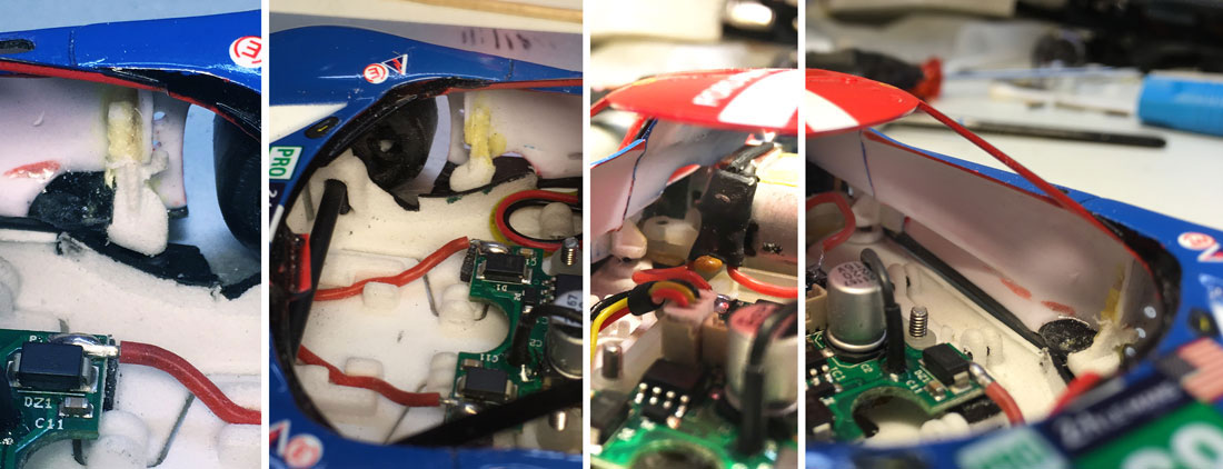
Later versions had a more controllable set-up with a holder for a grub screw incorporated on the chassis. The picture below shows how I glued the 3DP
body supports into the body:
Tacked in place with some thick superglue and covered with neoprene glue to secure it in place, should the flex of body, during a crash break the
rigid bond of the superglue.
My base set-up for almost all my cars is always to adjust the grubscrews so that the body rest squarely on 4 points evenly.
C.o.G or Centre of Gravity
As a rule of thumb, you'll want it as low as possible. So remove material at the top of the body where possible, vacformed windows etc etc. all that
stuff has been covered in my previous post.
Before we switched to the Ford as a plan B, I'd been working on the BMW M6, just one look at them side by side and you can easily tell which of the
two had a lower C.o.G.
The lower you're C.o.G the less prone the car will be to tip over on corner entry. And with the lightweight parts and body supports the Ford was rock
solid in that area, better and more stable than the M6.
So you could carry more speed into the corner. But when we ran the two side by side, mid corner and on the corner exit it felt like the M6 had more
grip.

Inertia & weight transfer
Now at this stage in testing the Ford needed balast in the body to get it on the 19,5 gr min weight, which we had placed low in the body. So it looked
like we'd lowered the C.o.G too much?
Indeed we had, because when we moved some of the balast higher up in the body mid corner grip improved immediately, corner exit remained the same
though.
When I checked the body after some test runs I also noticed we had more tyre deposit in the body than on the M6 and that the tyre wear on the Ford was
higher.
We had to much wheel spin coming off the corner. So here's the last bit of set-up trickery we used to get more traction coming out of the corner.
We had cut the diffuser from the chassis and mounted it on the pod to solve the ground clearance issues.
We were running the Ford with a bit fair amount of body float to allow it to rock and use the weight transfer to load the chassis.
But as there was now no more "chassis" behind the rear body supports, there was also no contact point behind the body supports to transfer weight to
the rear axle.

Then I remembered how Nick de Wachter had used a big block of soft sponge mounted on the back of his Dome chassis to generate more grip.
During acceleration the body would tilt backwards and make soft contact with the sponge and via the sponge would transfer weight onto the rear of his
chassis.
So I took a piece of foam rubber glued it on the diffuser where it would just clear the of the rear of the body.... and whoa, I now had much more grip
coming of the corner.
(if you look close you'll be able to spot the first foam test set-up in the centre image at the bottom of this post )
So the principle worked, all we needed now was a way to control and adjust the moment of transition.
As luck had it Stefan Nalbach had incorporated two body supports on the diffuser of his original chassis design. So all I had to do was glue two
pieces of foam in the body directly above the supports.
I covered the foam with some sheet plastic to keep the grub screws from biting into the foam...et voila, we could now adjust the amount and timing fo
the weight transfer under acceleration.
Ford GT LM Set-up: Lessons learned the hard way
So here's the final bit on set-up, prior to Le Mans all our testing had been done on the permanent Suzuka track, which is a challenging track with
chicanes, slow, medium and fast corners and a pretty decent straight.
To accustom ourselves to the longer gear ratios we run at Le Mans we used those in testing instead of the shorter ratios better suited for the Suzuka
track.
From experience we knew that if a car set up like this ran well @ Suzuka it would also run well at Le Mans.

During our testing we had run both SW chassis with different off set pods. Testing the slot.it 1,0 mm offset and 0,75 mm off set back to back. They
were both fast, but the 0,75 was just a bit easier to drive.
It had more flow, it would roll easier into the corners. The 1,0 offset had better brakes, more aggressive acceleration but also needed more work to
keep it flowing through the Esses.
Lennard and Nick (Helmich) were faster with the 1,0 offset, Marc and I were faster and more important more consistent with our laptimes with the 0,75.
With Wayne and Stephen not being able to test run the car until we were in Henley, I was convinced the 0,75 pod would be our best option.
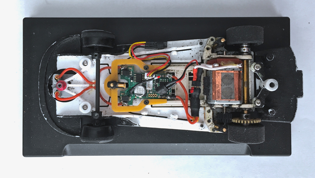
Well...I was wrong!!
This is written of course with the benefit of hindsight...and after having raced the Ford GT LM at Le Mans... and the Rock Bull ring, two very
different tracks compared to Suzuka.
Not being able to concentrate on back to back testing of both offsets at Le Mans (caused by our controller problem) did not help, nor did the added
stress of having to finish the lights on the race body etc etc.
But in all honesty, I just was not sharp, I wasn't on the ball, even though the signs were there. They say even a donkey does not fall in the same
hole twice... but I did.
The previous year Ditslot I3D had run their Ford with a 1mm offset, and even though Stefan (Kievit) and Lennard had been faster with our Corvette
(running a 0,75 mm offset) Ditslot had been more consistent.
This year even after we finally got the Ford sorted and were running well, we were being outpaced on consistency by the Posillipo Ferrari... and the
Prospeed Corvette. Both running bigger offsets than us.
Now I had no reference times for the Posillipo car, but Prospeed had tested their Corvette with us at Suzuka and even if you were to take in account
the home track advantage...
...the Ford had been quite a bit faster. blink.png

After Le Mans I did the usual post race inspection, found the chassis to be in perfect running order. During the race we did notice that we had much
more wear on the right braid than on the left.
We had the issue on Sunday morning with the right front wheel binding and discovered that it had also worn down so much that the plastic rim was
visible.
And even on the spare axle we fitted ( the chassis picture above was taken during the postface inspection) wear on the right was much more than on the
left.
It wasn't until I took a real close look at the body (with just the windscreen wiper, a mirror and its left skirt missing) that I noticed that the
right rear body support tab had come loose.
Loose as in being able to move up and down a bit, with just the neoprene glue keeping it fixed to the body.
Apparently the Ford had been hit hard on the left side, most likely at Mulsanne corner which took off the skirt (because that's were after the race I
had found it).
This crash most likely worked loose the right rear body support. As a result the weight was transferred unevenly on the chassis. Uneven weight, uneven
wear..but we made it to the finish.
After Le Mans my slot race focus shifted to the Oreca LMP1 prototype that we hoped to get ready for the e-csd 24hrs end of June, and when that was
cancelled, shifted to the development of the LMP2 version ready for Rockingham.
During that time I took the Ford for a couple of test laps and immediately noticed that it had no brakes and no torque, even after changing to a
gearing more suitable for Suzuka.
I put the car on the magnet Marshall and compared the values to what they had been pre Le Mans, yup, the motor magnets had been cooked by the long
15x28 gear ratio.
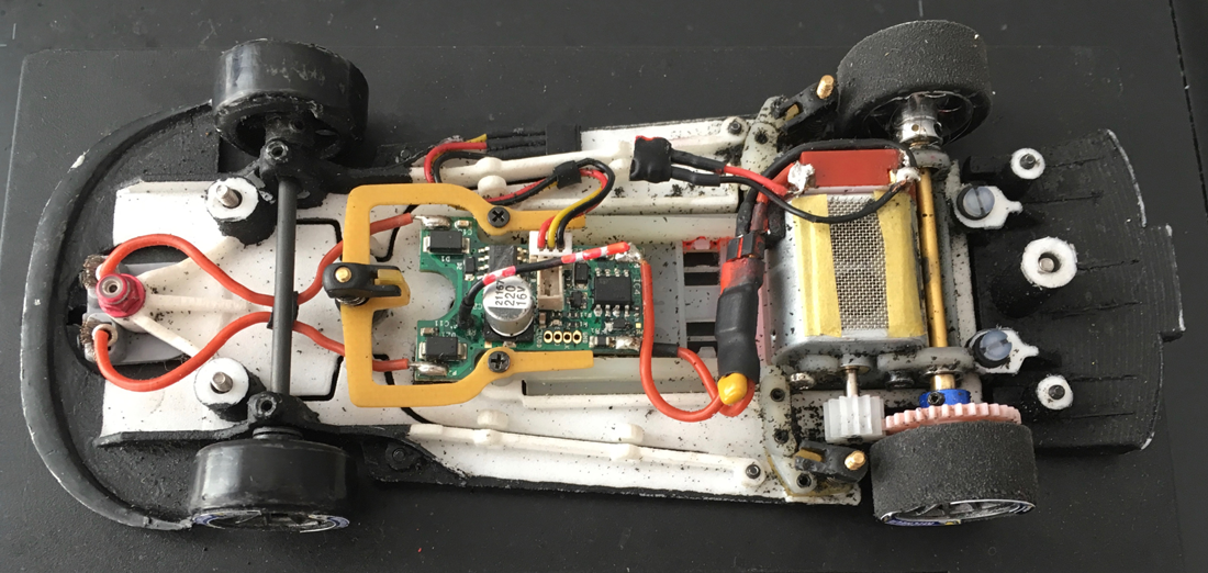
Down Donkey, down
Time flew by and all of a sudden Rockingham was right on our doorstep, time to give the Ford a major once over. We'd raced at the Rock Bull ring last
November, nice track.
Relatively flat (at least for a temporary track), medium length straights. One long straight with a tricky braking area with an LC smack in the middle
of the brake zone.
Three sets of hand out tires for just 6hrs of racing. With the lessons learned from Le Mans I had no intention of being a donkey again.
So I decided to set-up the chassis with the 1,0mm offset and a way shorter gear ratio, but no time for a quick test session @ Suzuka.
Upon arrival at Rockingham the Ford ran well pretty much traight out of the box, even with the 1,0 offset it was easy to drive and had a nice flow
through the corners.
Stable and consistent more or less what we had experienced with the 0,75 pod @ Suzuka. question.gif
Still needed a bit more brake so dropped a tooth on the pinion. On pace the Ford was just as fast as the leading LM P2's and even matched the speed
of most of the LM P1's.
Even our newest Danish team member John Anderson managed to put in some pretty decent lap times after he had become accustomed to a new track, a new
car and a new very demanding team captain.
We had to pit just two times for repairs, once after I'd hid a desolated car under the bridge at full speed: soldering on one of the light kit lead
wires had broken.
And once as a precautionary repair as I'd noticed one of the side skirts had come loose after an other crash. This time I was on the ball.
Back home the post race inspection showed both body and chassis to be in good health no damage, even wear left right on the braids, the front and rear
wheels.
We had used one set of N18 during the first 4 hrs with just 0,6 mm wear (0,15mm p/hr). Switched to the F22 for the last two hours and ran those down
to 19,6mm, (0,5mm p/hr) yikes.gif
Horses for courses
Two weeks ago I ran the Ford @ Suzuka again..and guess what... with the 1,0mm offset and same set-up, way to much brake, way to much and aggressive
acceleration and hard to get a nice flow through the corners.
And then it dawned on me, even though a car set up for Suzuka would run well on Le Mans and the Rock Bull ring there were similar differences between
them and Suzuka.
1 Le Mans and the Rock bull ring are temporary tracks, and have less tyre deposit & thus less grip than the permanent Suzuka track.
2 The corners of the Le Mans and Rockbull tracks are flat or at least not banked in the way most corners are at Suzuka.
3 Besides banked corners the Suzuka track also has more undulations where the track rises and falls as it follows the terrain. As such it requires a
bit more ground clearance.
The result of these 3 combined mean that @ Suzuka you need to run a smaller offset on your pod and with the higher grip levels can get away with a
lower gear ratio.
So gents, mental note for Le Mans 2020 and all those who plan to take part in the Suzuka 6hrs...horses for courses gents, horses for courses wink.png
When the flag drops...the bullshit stops?
Time for some closing words on our 1/32nd Ford GT LM, its road to Le Mans...and then a bit more. Future projects are calling, a renewal of plan A.
But if there's one thing prepping testing and racing the Ford over the past six months has learned us... its always good to have a plan B.
For Ford running their LM GT had always been a 4 year project, winning Le Mans on its first outing and then Daytona, they had nothing left to
prove.
Being caught out on the wrong side of the B.o.P several times didn't motivate them to extend the program nor do they seem to be interested in moving
on to a Hyper car.
Their plan B of extending the life and success of the GT LM in the GT AM class was met with some peculiar and very strict regulatory measures by the
ACO.
They say when the flag drops...the bullshit stops, while that may still be true if you cross the finish line winning (your class) in 1/32, but at Le
Mans.... unsure.png
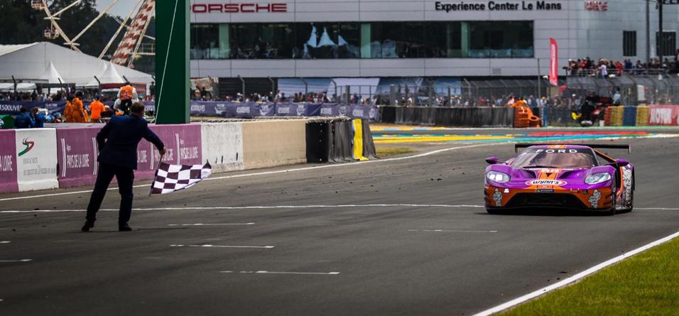
With kind regards
Tamar
P.s: A big thank you to all who have helped me with this project, special thanks to Simon Owen from Hornby for going the extra mile, providing us with
spare cars..amongst one very special one.
Philippe Laudet for his outstanding Z-machine light kits. Slotfabrik for the decals and C&C designs for the decal plan B.
And last but not least, a very warm thank you to Stefan Nalbach for the endless hours of work, redesigning the 3DP ProSpeed chassis every time I would
come up with yet an other modification.
|
|
|

|
tamar
Posts: 804
Registered: 5-1-1989
Location: Gouda
Member Is Offline
Mood: A new beginning 
|
|
posted on 6-6-2021 at 16:05
|

|
|
Ford GT LM: Play it again Sam
When my part in the Organisation of the DiSCA Finals @ Igualada become more time consuming than provisioned, Plan B, a.k.a the by now
trustworthy #18 Ford GT LM had to be called upon once again.
As the Ford had been one of the test mules for the Policar evaluation we did on the Slotracing2go track so I had a base set-up to start with, but that
test run also reminded me that there still remained some
unfinished items on my to do list.
To do list: Rework Lights wiring
Clean up and rework the lights wiring was one of them. May look like small detail stuff, but bad wiring can actually seriously fuck-up your car's
handling.
And its almost always something that you notice post race and makes you think "will do that for the next one". And then you forget about it until
its too late, and off course and you have to run with it again.
So...not this time mate.

On the left, lights wiring after Rockingham, on the right after Igualada, also noticeable here the front splitter now attached to the body
On the Ford we had two sets of wires crossing over from left side of the body to the right. The red & blue were for the green position lights, the
yellow and blue were for the Flaming exhaust led's.
During the hectic 05:30 hrs Saturday morning fit the lights before the lM 24hr race session..both had been cut a bit too short.
Not by much, but I later discovered that they did interfere with the body float. As the Finals would not have a night session I carefully removed the
position lights and wire from the body.
Did not want to miss my flaming exhaust pipes (great indicators of you brake points when you car runs parallel to your driving position) so I rerouted
those.
I also remounted the Z-Machine light chip on fresh pads a bit higher in the body. Turned out that the Capacitor kept the body from resting square and
flat on the body supports.
Last but not least. I used more flexible wires for the connector to the chassis. The stock ones on the Z-machine chip can be a bit stiff, stiff enough
to lift the 20gr body from the supports.
With the chip remounted and cleaned up (softer) wires the body now rested rock solid on the 4 support mounts.
To do list: Remove Front Splitter from Chassis.
This modification had intentionally been left on the to do list. In general I prefer to run my cars with the front splitter attached to the body and
not on the chassis as with most RTR cars.
But as Stefan Nalbach had copied the Scalex chassis in its initial ProSpeed design, we ran the Ford @ Le Mans in this configuration..what can I
say...it makes one hell of a great bumper.
As John Ny would join the team and make his debut in DiSCA racing @ the Rockingham 6hrs, I though it might be best to keep that bumper for one more
race.
John proved himself as a very stable driver and didn't put a scratch on the car so when it became celar that we would run the Ford again in Spain..it
was time for the splitter modification.
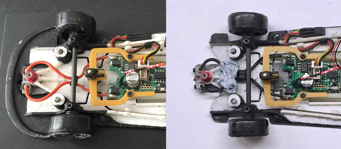
The reasoning behind this modification is that I want to be able to set, adjust and control, body & chassis movement independently.
On the Ford that big splitter works great as a bumper, but it also works as a snowplow, grabbing every unevenness on the track.
It would also lift the front of the body every time the guide encounters a bump on the track.
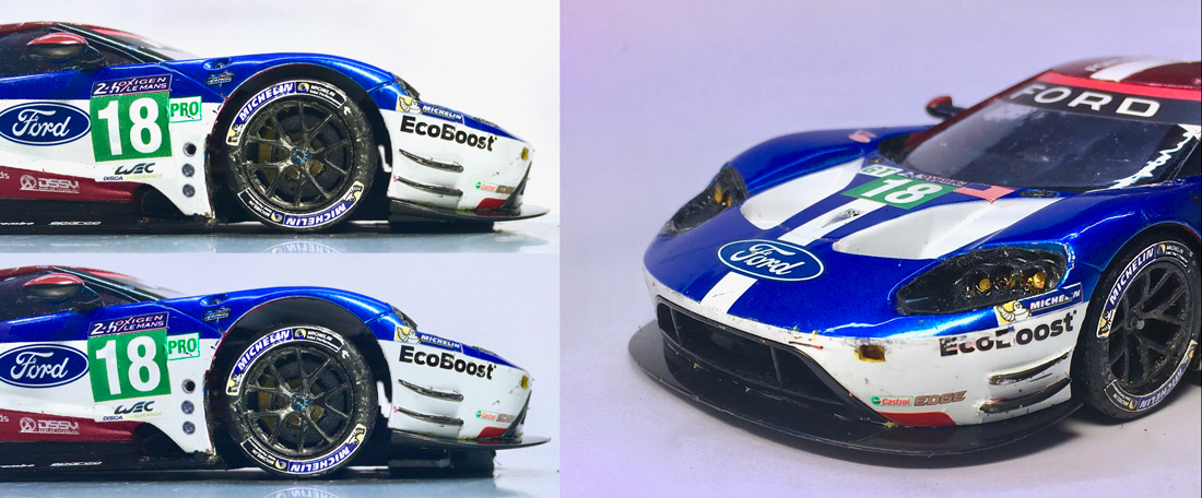
So off came the 3dp splitter from the chassis, and onto the body I crafted the Splitter I had cut from the OEM Scalex chassis. (also see top picture
right with the bodies on the scale)
Works better and looks much nicer. As usual my preferred method to attach the splitter to the body was BisonTix Neoprene glue. Tough as hell but it
always remains a bit flexible,
just enough to be able to give a bit in a big crash. Picture above right was taken after the Igualada race, the splitter did take a few hits...but
didn't move an inch, not even a 1/32 inch.
DiSCA WEC Finals, Catalunya 6hrs: I just love it when a Plan ( B ) comes together.
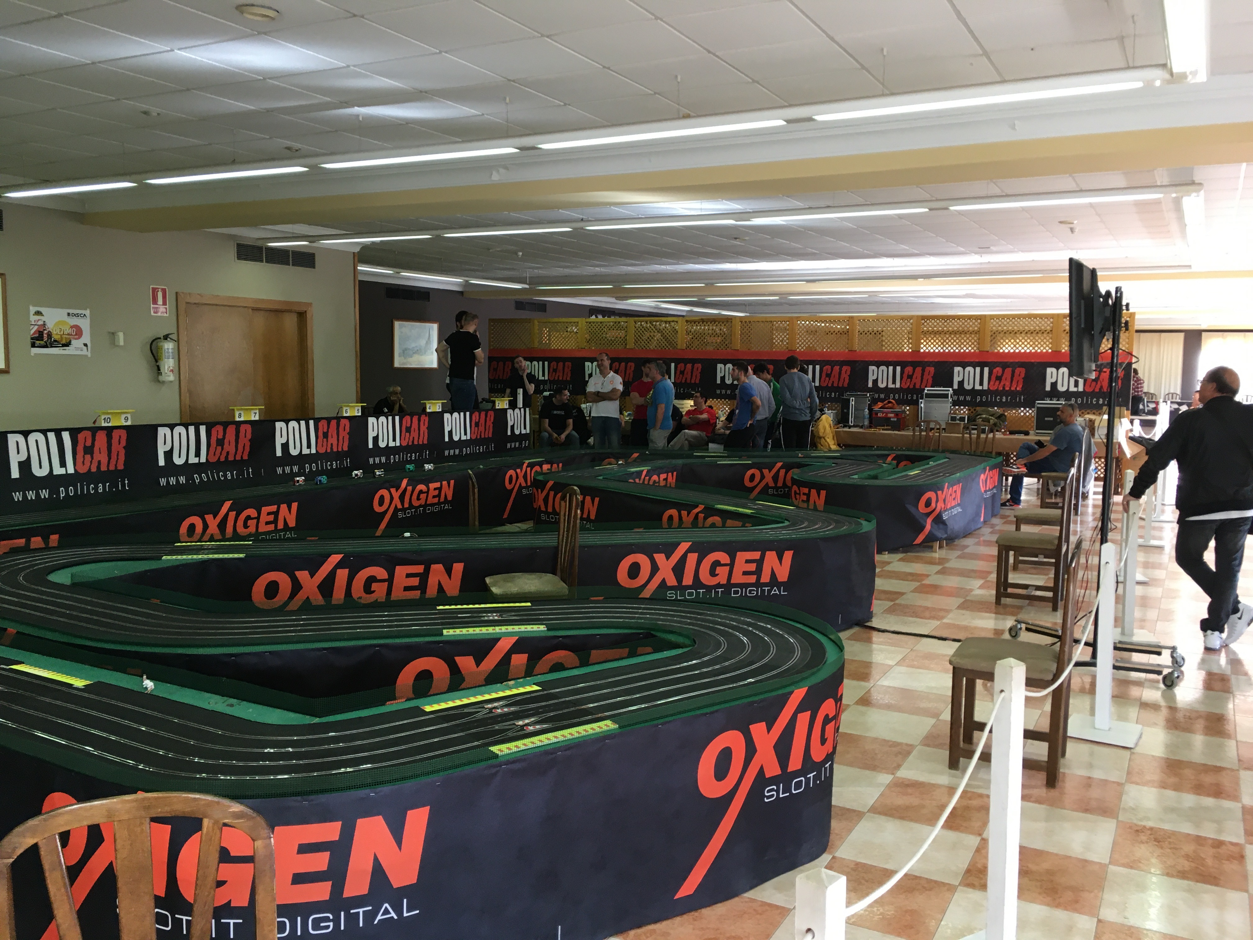
With all the mods and detail jobs done the Ford was ready for its first run on the lovely Catalunya Policar track. Nice track, nice lay-out with some
wide open corners some of which were taken almost flat out.
But surprisingly during the practice sessions the Ford struggled a bit for grip, mostly on the 2nd half of the circuit. It was still one of the
fastest GT's, but we had much less grip than usual compared to the Flat-6 engined LMP1's.
With hindsight and for reasons I have explained in more detail in
[url="https://www.slotforum.com/threads/disca-wec-gt3-european-final-igualada.190749/page-3#post-2284725"]this post[/url}, we lacked a bit of
magnetic downforce.
The smooth and flat Policar track gave us a higher ground clearance as the distance between the motor and the track rails was bigger than on Ninco.
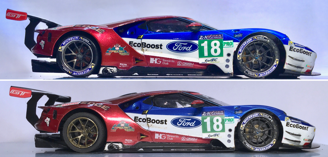
Top picture the Ford GTLM on fresh 20,6mmø trees, Bottom picture with the rund down 19,2mmø N18's after 6hrs of hard racing...but still with
ample GC under the diffuser.
After running for 2,5 hours on the same N18's did the Ford finally started to behave. With the SW MX16 configuration the lower the tyres got, the
better the car handled.
So when I handed the car over after 3 hrs Marc (Wiggers) asked should'nt we change tyres? A quick check for GC showed we had more than enough, so we
ran the whole 6 hrs on the same set of N18's.
In fact he smooth and flat surface of the Policar track allowed us to run the tyres down from 20,6mmø to 19,2 mmø with still ample GC at the end of
the race.
I tested the magnetism of Ford GT pre and post race and it went from 1773 ut at a GC of 1,7 mm on a tech block, to a whopping 2330 ut with a 1mm
GC.
Off course the only reason we were able to do so was because our Diffuser Mod to mount it on to the motorpod.
Had it been attached to the main chassis we would have been dragging our ass on the track after 3 hrs.
As Hannibal used to say I. the A team:" I just love it when a plan comes together."
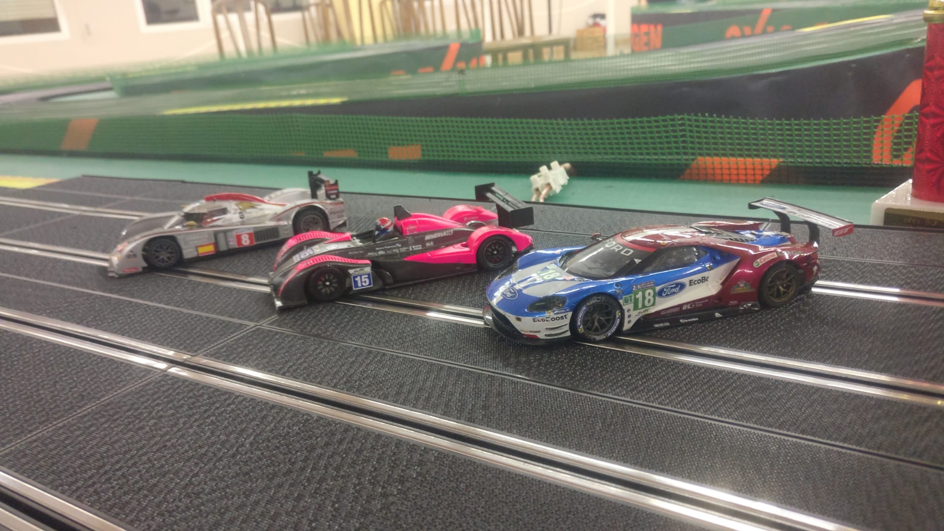
With kind regards
Tamar
|
|
|

|
tamar
Posts: 804
Registered: 5-1-1989
Location: Gouda
Member Is Offline
Mood: A new beginning 
|
|
posted on 6-6-2021 at 16:19
|

|
|
Ford GT LM, the road to Le Mans 1/32, the Sequel
Less than 3 weeks till the DiSCA Le Mans 24hrs, sounds familiar? Well yes....it does.
Just when she though she might be able to enjoy her retirement, no more being plan B. Just one more Mission8 test to go serving as a reference car
...
...and all of a sudden she's booked for a whole new season. The main star in "The Road to Le Mans, the Sequel", winning its class at the Suzuka
6hrs as a warm up.
So if you want to follow the latest episodes of the "Sequel"...I'll post them here.
 . .
to be continued
with kind regards
Tamar

The Ford GT LM coming out of the 130R behind the now benched SV8GTE and in front of the ProSpeed C7R
|
|
|

|
tamar
Posts: 804
Registered: 5-1-1989
Location: Gouda
Member Is Offline
Mood: A new beginning 
|
|
posted on 6-6-2021 at 16:45
|

|
|
Taking stock, clearing out the cobwebs.
So we'll be racing the Ford again this year @ Le Mans, in just a bit more than 3 weeks..... Time to take stock and clear out the cobwebs.
Because although the Ford has served us well last year with good results, there's always room for improvement.
After the 2019 Le Mans 24hrs we had the following bullit list with attention points.
- Rear Wing kept coming off
- Bit of overweight.
- Lights, Hard to spot the car from the rear specially through Dunlop/'S de la Foret/Tetre Rouge section.
- Motor ran hot: Shorter gearing, Improve cooling,
- 0,75 offset gave to little magnatraction compared to competition (that ran 1,0 offset pods)
- Frontaxle too short, Front axle stuck solid after a crash as right wheel moved in on Axle.
Some of the items on the bullet list have been taken care of and race proven during the rest of the 2019/20 races (like the rubber wingsupports and
the 1,0 offset pod).
Clearing out the cobwebs
So the first thing I did to the Ford after last sunday's test was to give her a good clean up and inspect the body.
No structural damage after one year of racing, few scratches on the nose, striping on the roof showing some wear, no cracks, damage etc etc.
The Bison Tix neoprene glue really worked well and held all parts together. In some area's I had applied it exessively, or just poured it on in a
quick race repair, so I set out to remove some of it.
Tough as hell and still flexible even afyter a year, meaning that with the right amount of applied force...it comes of clean without leaving a mark on
the body.
I cases where the Neoprene glue's bond feels stronger than the part you want to remove it from...a Q-tip dabbed in cleaning petrol will soften the
glue...but...do check if the underlying surface can handle the Cleanig petrol.
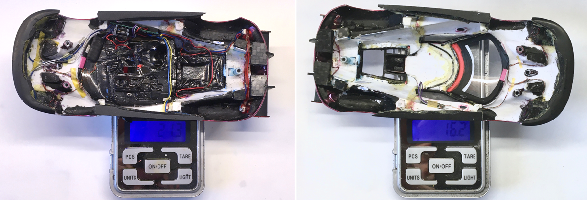
On the left the body after clean up, as I wrote a bit overweight...by DISCA 2019 standard, but for Suzuka we actually needed to add 0,7gr balast to
comply with the 2020 rules.
On the right the body with the Z-machine lightkit and interior (carefully) removed. Cleaned and Polished the windows on the inside as lots of tyre
gunk and debris had assembled there.

Removing excess glue and a tiny bit of redundant plastic in the roof dropped the body weight by 0,1gr to 16,1gr sans lightkit and interior.
Every bit counts as to address bullit point 2 & 3 well be adding more lights to the body. At lest twice the weight of what's on the scale in the
middle.
So that's at least 0,4 gram we need to find, and on the right scale is the most likely place we might reclaim that weight. Shorter, lighter (and more
flexible) wires and trimming the taillight lenses.
Replacing the capacitor for a lighter version (from slot.it) alone should give us 0,4gr, but need to test if the Z-machine chip will still work with
the lower capacity of the slot.it goldcap. (z-machine 0,33f, Slot.it 0,1f)
Indentification lights, Friend or Foe

Well this the one item where despite our best efforts our Ford seriously lacked "1/32nd realism" because at Le Mans there's no mistaking the Fords
at night.... from any angle.
(here green but identification color for the #68/#18 is red) Our 1/32nd Ford was hard to spot from the rear specially through Dunlop/'S de la
Foret/Tetre Rouge section.
Our aim not to overdo these identification lights (not wanting the disco light set-up as ran by Ditslot in 2018) backfired as the leds we ran were not
visible enough.
So in the picture below you can see the test set-up for the 2020 identification lights. Will mount these high-up underneath the Ford "wings" but
will need to black out the inner surface so the led won't shine trhough the plastic.
The mini Z-machine brake leds give a nice diffuse light.
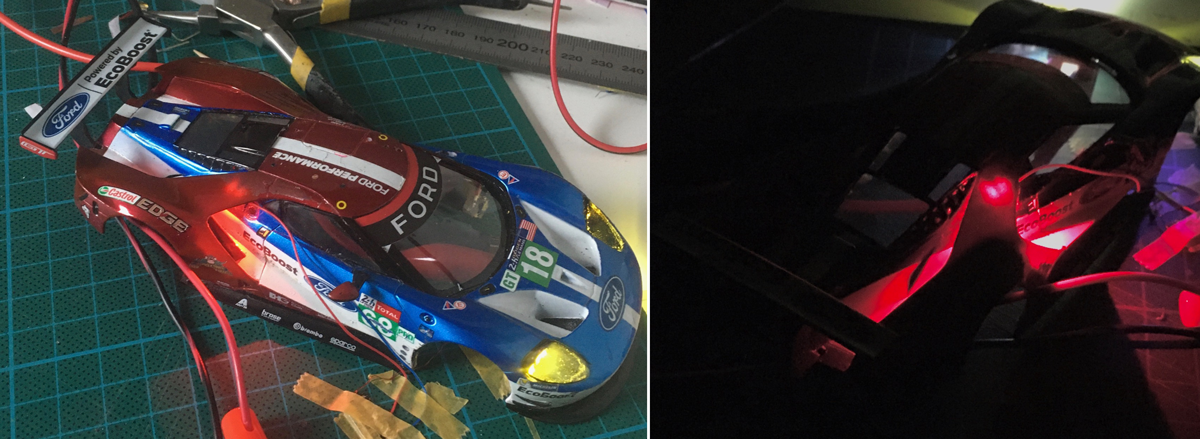
Actually all Z-machine leds give of diffuse light, while that's good for most lights its not I.m.o. for the headlights.
Although the Ford with its tripple headlights was easilly recognisable from the front...I wanted to have light beams in front of the car.
So instead of the regular "diffuse" smd leds, "old School" 1,8mmø leds with clear lensses (see bottom right) will be mounted in the foglights.
Still working on the wiring plan, the plan is to have the headlights connected to the Z-machine chip fed by the motor wires and feed the foglights
from the O2 chip.
This way I can give the foglights a bit more juice (3v on/off switchable) ...
The O2 chip will also be used to light up the numbershields
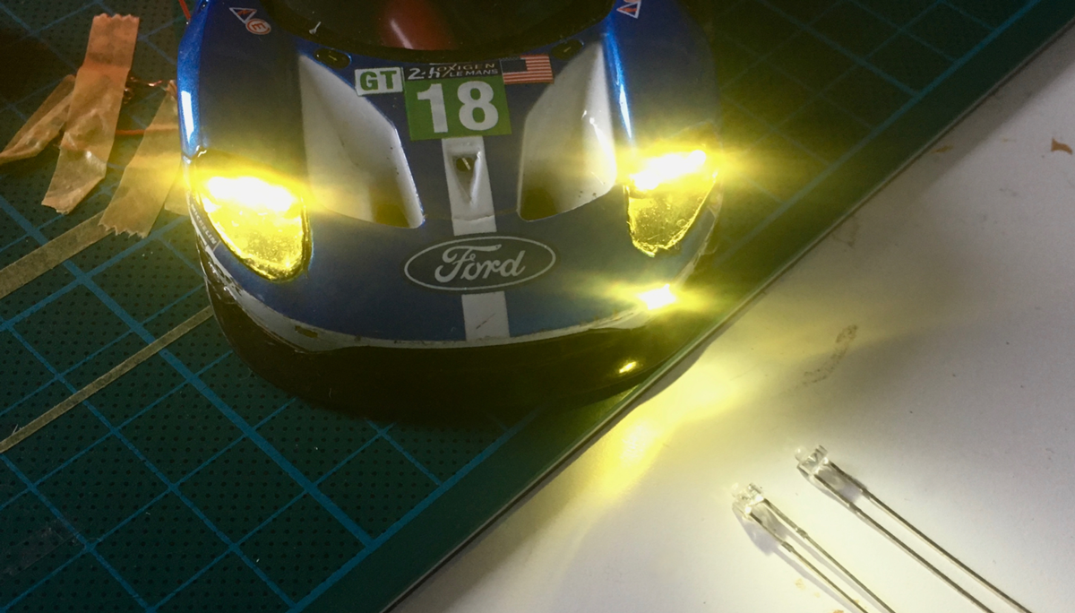
Lots of paint
Say what you like off Scalex cars, but their paint jobs are meant to last, 48 hrs of hard racing and hardly a scratch on the Ford...but that needed to
change.
As the only way I would be able to get any light to the numbershields required digging in deep and carefully scratch away the paint.
Did not do this free hand off course, masked of the body around the shield and started scraping away the paint...carefully, layer by layer
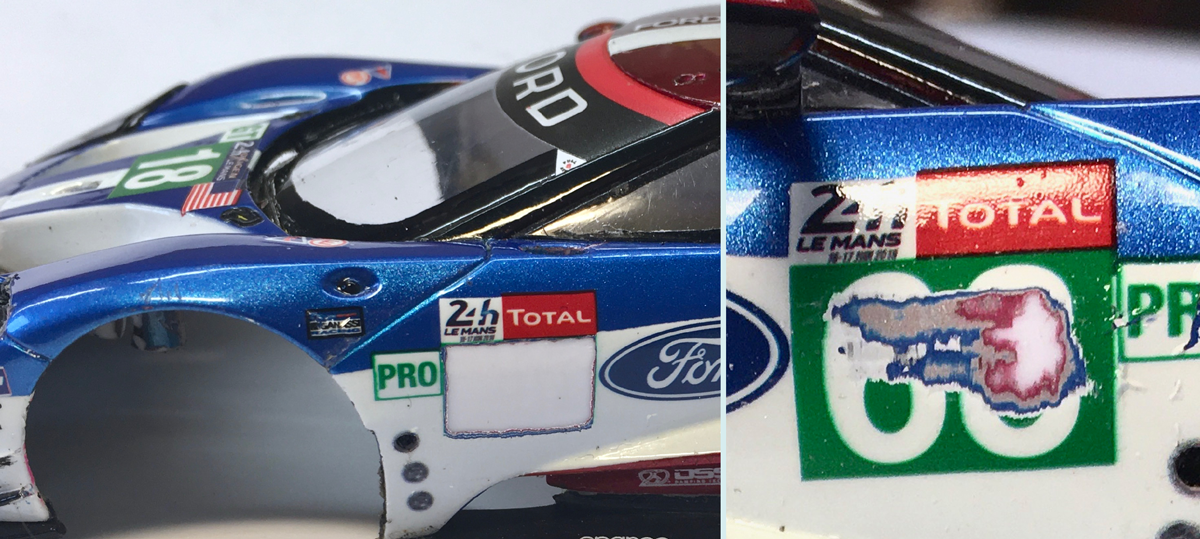
As you can see picture right, there were quite a lot of them, The tamponed print, then the dark metallic blue, then a silver layer, then metallic red
and then finally bare white plastic.
So no masking, no extra's, just a bit of elbow grease, two LED's (might spread them further apart) and a paper sticker (decal or vinyl would do the
same job, maybe even better)
More info on the SMD led's I used can be found here:
https://www.slotforum.com/threads/number-lights.194389/#post-2313881
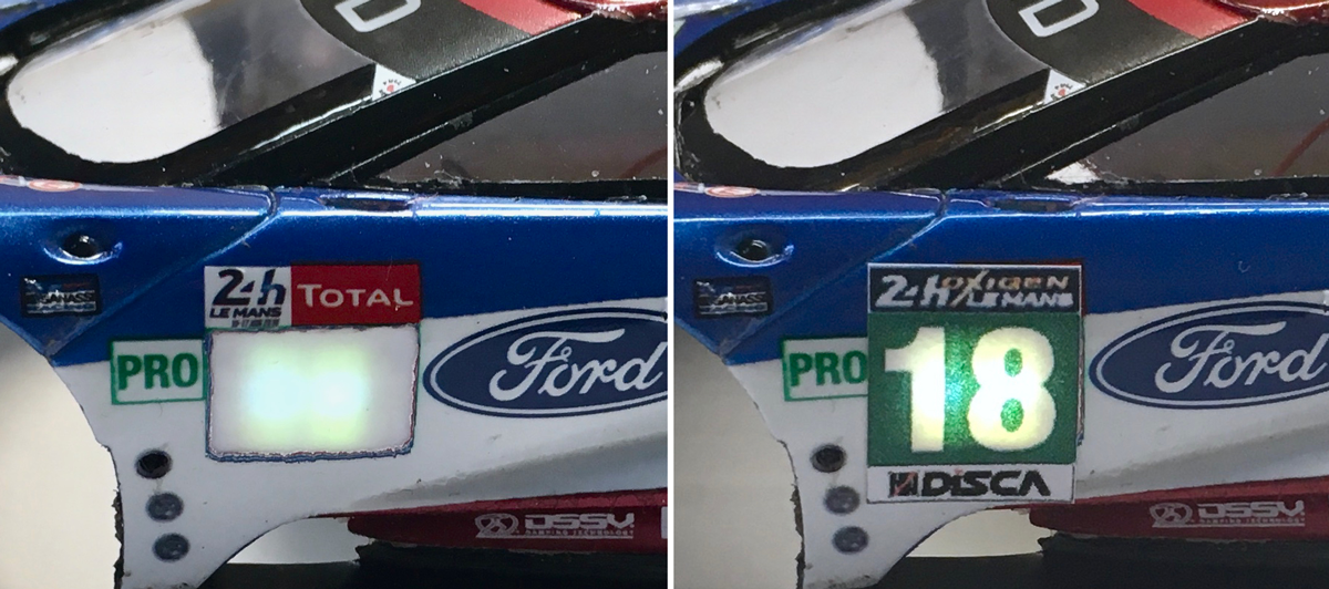
to be continued:
With kind regards
Tamar
|
|
|

|
tamar
Posts: 804
Registered: 5-1-1989
Location: Gouda
Member Is Offline
Mood: A new beginning 
|
|
posted on 6-6-2021 at 16:52
|

|
|
Road to Le Mans cancelled, at least for now
This afternoon and with great pain in my heart I have withdrawn the Mission8 team entry for the DiSCA LM 24hrs April 4-6 2020.
Main reason for the withdrawal...the COVID -19 situation.
This has been an unanimous team decision, in full understanding that this would make not only our entry, but also the already paid entry fees null and
void.
We hope that this will compensate for any damages resulting from our late withdrawal.
We have taken this decision while it was still ours to make, we wanted to be Pro active in this situation and not await further developments.
We wish DiSCA and all the other teams and friends all the best in these tasking times. Take care, stay healthy.
with kind regards
Tamar
p.s. Eventhough we've cancelled our trip to Le Mans, this story and post here are still
to be continued
|
|
|

|
tamar
Posts: 804
Registered: 5-1-1989
Location: Gouda
Member Is Offline
Mood: A new beginning 
|
|
posted on 6-6-2021 at 17:02
|

|
|
In the mean while, let me share with you some of the work I did under the hood, this was done last week when the go, no go situation on our the road
to Le Mans was going on.
As some of you may remember, we had two chassis prepped for Le Mans last year, the MK 2 with the 1,0 mm offset and the MK2 evo with the 0,75 offset
pod.
We raced the MK2 evo at Le Mans, but switched for the rest of the season to the MK2.
So last week I decided to give the MK2 evo a good once over.

Ford GT LM Prospeed chassis MK2, pictured above just after the 2019 LM24 hrs.
Spend a whole evening to get the MK2 evo chassis to move and float the body like the MK2 does. Made me realise how much work had been done to that
chassis.
When I compared them sitting side by side on my workbench I noticed that every item on the MK2 chassis had been changed in one way or the other.
Minimal differences in height of the body screw posts, chassis edges shave just that tiny bit to clear binding iussues.
Guide ride height, front axle travel, Body supports, suspension travel and springs.
The list of mods I apparently had done...(and forgotten) just kept growing, improving the chassis bit by bit, race by race.
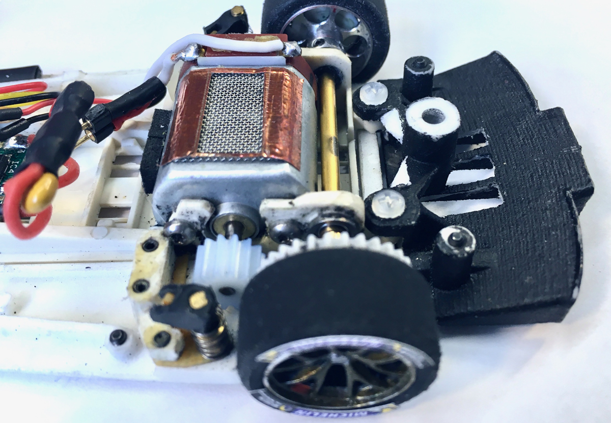
At the end of the evening I still wasn't happy. I'd gotten close...but just not close enough. Something just didn't feel right...
So...back to square one, disassembled the whole chassis and checked it on my chassis flatting plate...and sure enough, there I got confirmation that
the chassis was bend.
Wheter this was caused by running it in the LM 24 or just by handling/assembling it prior to the race...we'll never know, although with my experience
of how the M8 chassis got bend...I assume the latter.
Anyhow, this meant that Chassis MK2 was destined for a bath...and a slow cooldown in the oven.

In the mean while as the now straightened chassis cooled down to room temp, I started adressing items 2 and 4 on the bullit list. (bit of overweight
and improve cooling)
Some of you may have spotted the slot's I cut in the diffuser on the previous chassis image.
Like the M8 diffuser it saves a tiny bit of weight and the slots will help extracting warm air out from under the body.....but there's more to it
that just that.
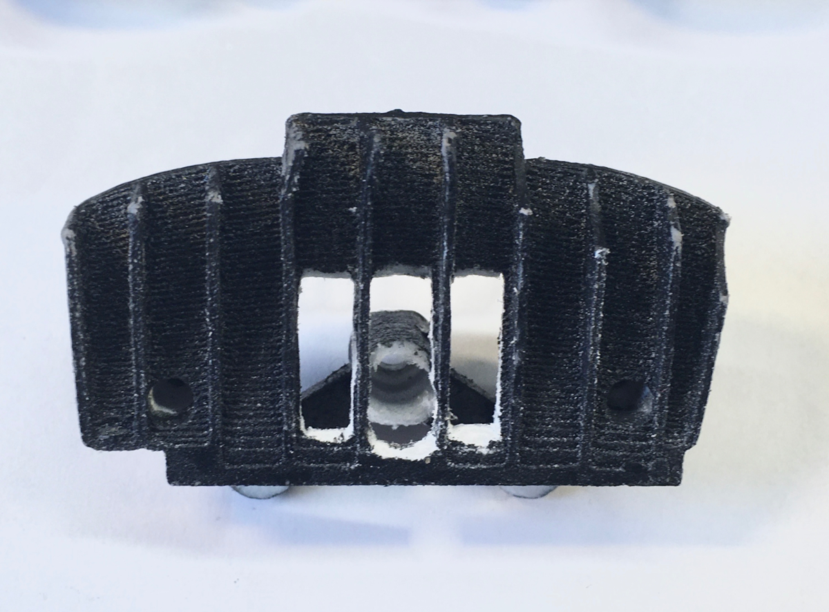
to be continued:
With kind regards
Tamar
|
|
|

|
|


