|
|
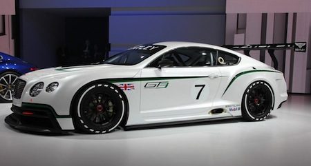 Back in September 2012, when Bentley unveiled the concept for their first race car in a decade, it made a stunning impression. Choosing the Continental as a platform for their GT3 racer caused many to either love it or hate it. Back in September 2012, when Bentley unveiled the concept for their first race car in a decade, it made a stunning impression. Choosing the Continental as a platform for their GT3 racer caused many to either love it or hate it.
As most would consider the Road GT is was based on, as a car more suited for a Cannonball Run, not the ideal weapon of choice to go GT racing. In the past 3 years the team of Bentley engineers have proved them all wrong, having developped the "Conti" in to a very potent package under the current GT3 regs.
For us 1/32nd engineers, creating a "competitive" Conti GT3 has been a bit more difficult task, at least such was the case until the summer of this year. Bentley Continental GT3 dimensions
Length: 4950 mm, Width: 2030 mm, Height: 1350 mm, Wheelbase (GT road car) : 2743 mm, Wheels: OZ Racing 18” x 13” rims, Tyres: 310 / 710 R18
Now there are two platform options to choose from, if you want to build a Bentley 1/32 GT3 racer, the Scalextric with a PCR chassis and The Area71 with the 3D printed body and chassis. This build report will focus on the latter, as my choice was to go for the package that I.m.o would have the biggest potential to go racing:
A light 3d printed body and chassis with all the tuning and suspension options of the proven NSR pod.
(But there will be some "guest" appearances for the Scaley Conti here as well.)
If the C7R is the equivalent of the American bald Eagle, then this must be the White Tailed Eagle, Brittain's biggest bird of prey.
Because that's the first thing you notice when you unbox the TA71 Bentley Continental GT3...its a big brute... but by no means a heavyweight
Overall proportions and stance of the car is very good. This is going to look so mean in British racing green.
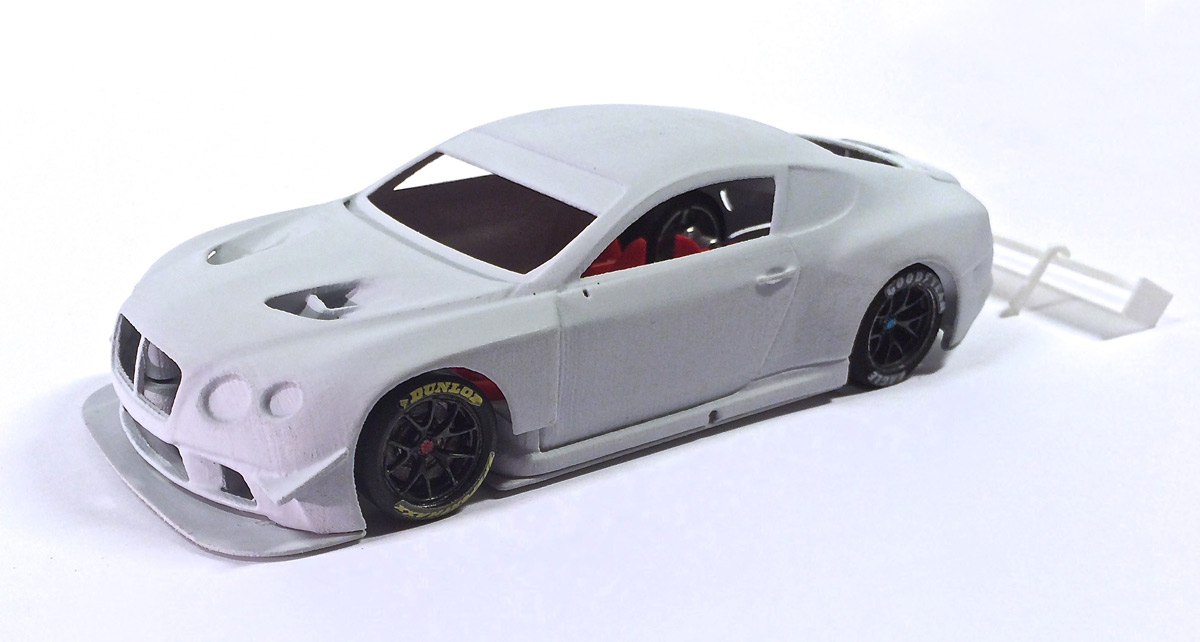
As you can see the first thing a did was to put the Brute on the biggest wheels I had (sorry for the mismatch of tyre decals
ø 20mm at the front, ø21mm at the rear. (smaller wheels would look downright silly)
IMG_5429.jpg
This is the first time I've had a look at the current level of TA71 post print processing.
On the bigger curved areas it looks very good and smooth. In its factory grey primer it looks very similar to the finish of the big 1/24 Japanese resin kits.
IMG_5433.jpg
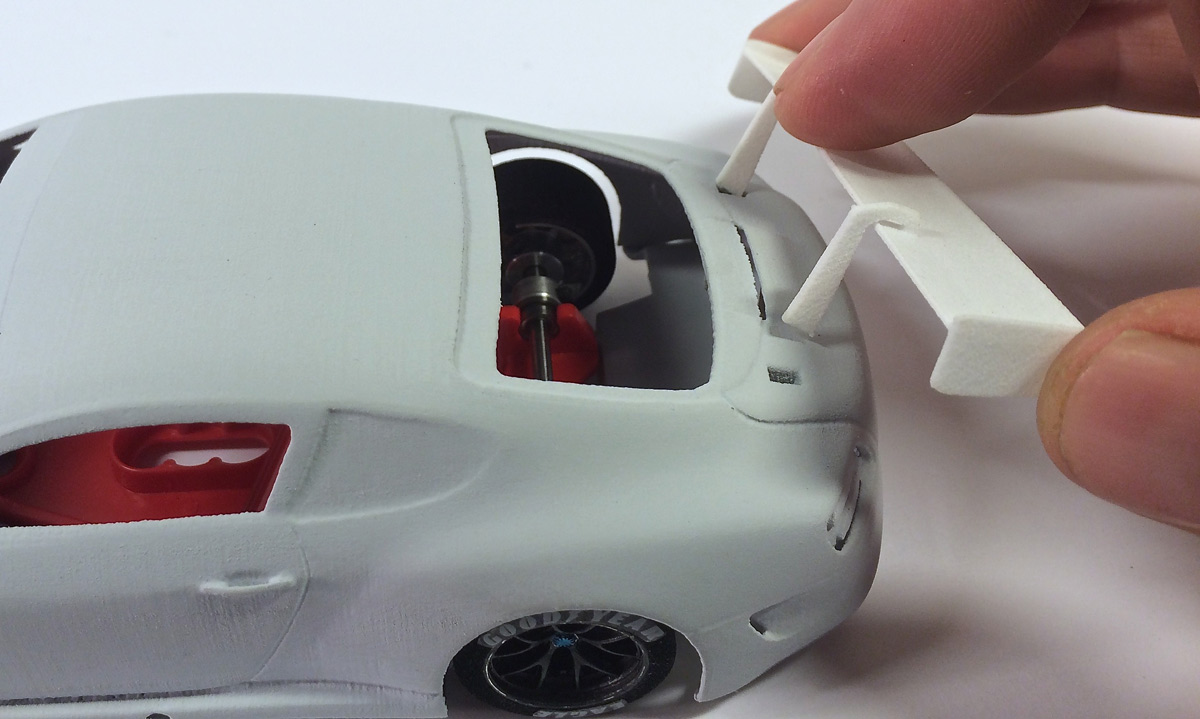
The rearwing and swanneck supports...they're a beautifull piece of 3D printing.
Niceley shaped, light and thin. Not only very good for the scale appearance, but also performance and crash wise.
It looks like the thinner they make them, the more flexible they become. So they can "give" in a crash and obstructive marshalling...instead of breaking.
The only problem I have with the spoiler is...it doesn't fit in the body (yet)
Apparently The Aerea71 made the wing mounts .2mm larger than holes on the body.
The intention being that after being primered you can file the end part and remove material until you get a tight fit that won't require glue to stay in place.
IMG_5454.jpg
Love the fine detail of the doorhandles, but do wonder why if The Area71 manages to print the mirrors and the windscreen wipers as separate items, why dont they do the doorhandles as well.
How am I ever going to sand the body under the doorhandles, at each layer of primer, paint and clearcoat?
I posted that question to Marco of The Area71 and it might me somthing they will consider in future projects.
Anyhow, the doorhandles are a fine example of how detailed their 3D printing has become.
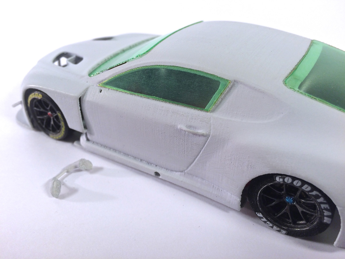
Lasercut windows are laser perfect, shape is good, fits like a glove. Nice note mentioning the need to clean the egdes of the slight discolorosation.
I think its very good of the Area71 to share such info with their clients.
Trail fitting the windows did howvere expose a slight post process sanding problem on small ridge that surrounds both side windowframes.
Near the windshield that ridge is still there, but the further to the rear you get... the more its been sanded away.
And what happened to the little rear side windows ?
IMG_5456.jpg
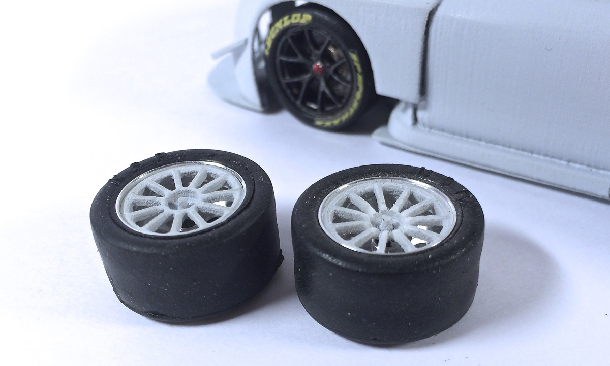
Ok so you guys know I have a wheel fetish....so this is a pet subject of mine.
I must say that for a SLS printed insert they look pretty good and the fit inside a NSR rim is perfect.
Centre lockingnut is a nice touch, but could have been a bit beefier....and the shape of the rim spokes.....hmmmm they looked a bit flat.....so I looked at some ref pictures...and ...
...I mounted the wheel + insert on the hudy and used some shrp knifes and emmery paper to change the profile of the spokes.
The one on the right is the modified insert. The spokes now angle deeper into the wheel.
IMG_5430.jpg
Ok so far so good, but now a few points of attention..and some (note) constructive critisism:
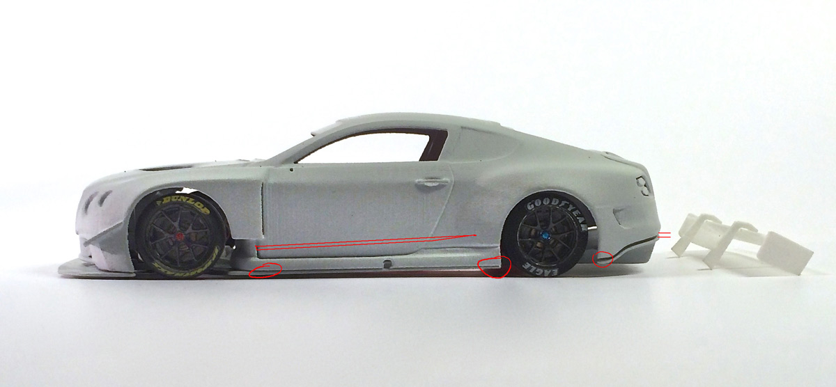
On the side of the car one little detail seems to be lost in the post process sanding.
There's a small but distinctive edge just above the sideskirts..you can still see traces of that line in the 3d print, but the edge itself is gone.
Secondly when mounted to the chassis my body sat at a slight offset to the left.
Its mininal, but enough to have the body left side, slide over the chassis, instead of firmly resting on top of it.
So its not just a scale issue, but also a performance one (no applied pressure on the chassis during body roll)
Then..there's a gap between the nicely shaped diffusser and the bottom edge of the rear bumper.
IMG_5435jpg
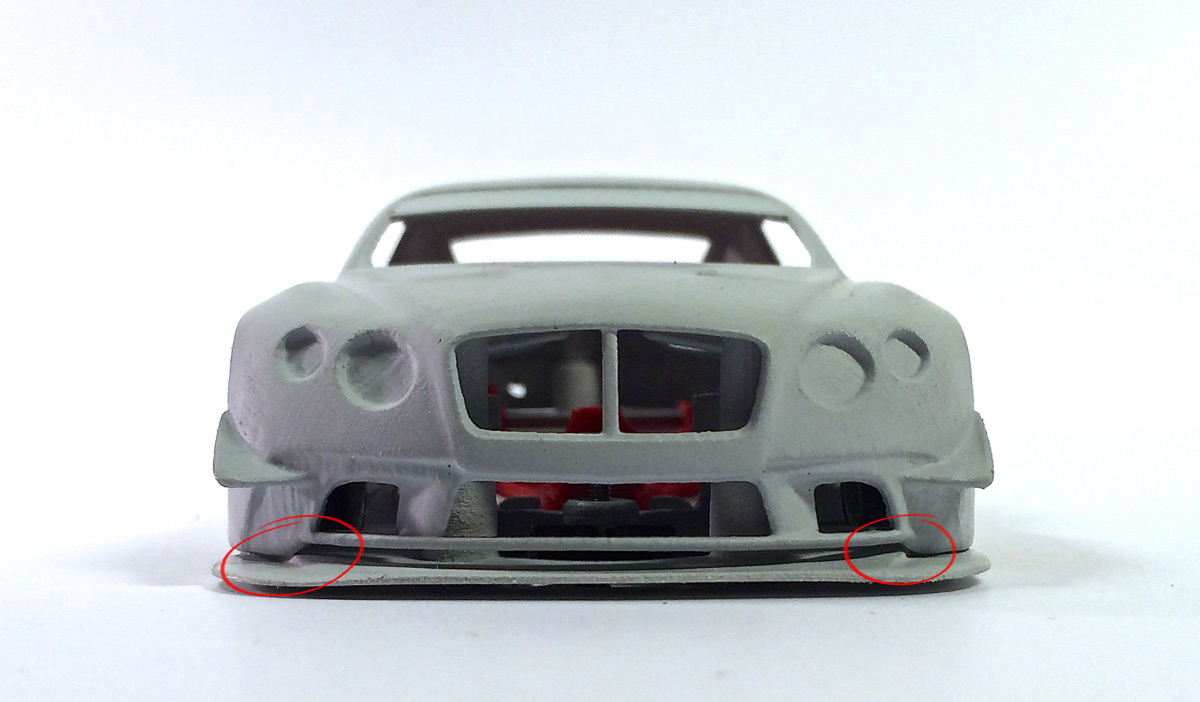
Again in front view, looks and proportions very good, Like the little piece of mesh that was supplied for the grille..but miss a bit of headlight detail.
And then there's also a slight tilt of the body to the left (right side on the picture)
As the body side skirts rest unevenly on the chassis this is causes a slight tilt at the front.
The step in the front splitter is very true to scale, but could be a bit more accentuated for slotracing.
IMG_5442.jpg
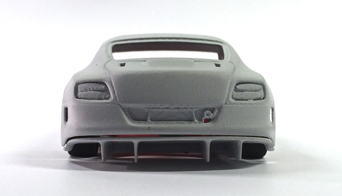
At the back the same tilt but in the opposite direction. Chassis is nice and straight. Maybe the body warped a bit during the final stage of post print processing?
IMG_5448.jpg
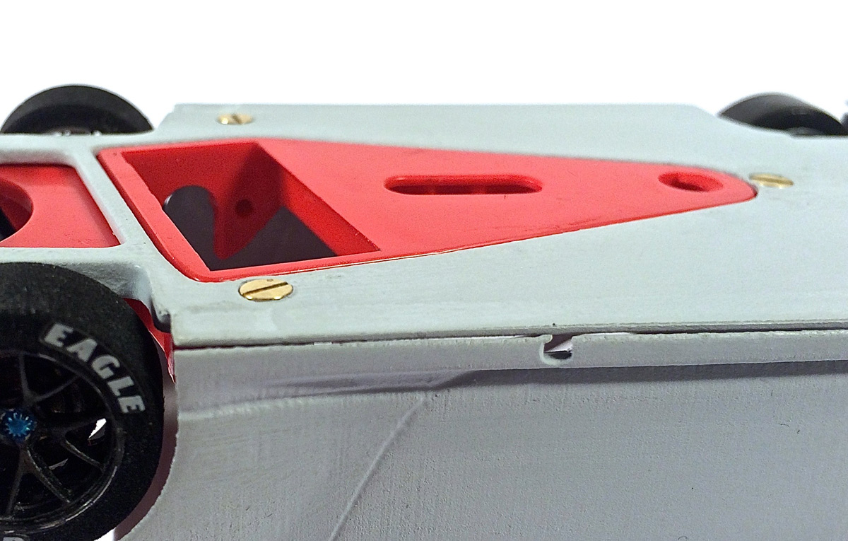
Chassis floor has a nice and polished feel, but primer residu collected in the chassis orfices makes tthem shallower.
As a result the side suspension screws stick out below the chassis floor.
There' are little bits of extra material sticking out into the pod aperture.
They push the pod to far back and to the right. I have removed them and now the pod moves freely up and down.
to be continued
with kind regards
Tamar
|
|


